This is the suspension portion of my build on the 47-59 section (Chevyrestoguy's '55 build).
I decided that I was finally going to bite the bullet and do an air-ride on my truck. I have been asking questions about air-ride for a long time. I do alot of my own fab work, but I needed some help on this one, so I enlisted the help of a buddy who owns a shop (Exile Fabrications, Apple Valley, CA, Mike Jones (owner) that specializes in this type of work. I gave him a outline of what I wanted the truck to do and turned him loose. Here's a cut/paste from my build of what we've done so far:
The plan was to remove the leafs in the rear and build a 3-link set-up with Slam Specialties RE-8 bags. Single 10 gallon air tank, 2 ViaAir 480 pumps, 8 valves. I want a slow-moving, quiet system. All the lines will be hard-lined. The front will get Slam Specialties RE-7 bags. It's not important for me to have the truck lay on the frame rails at full deflation. I just want to be able to raise the truck when I have to go over speedbumps, enter a driveway, or go down an uneven road. I've never had an airbagged vehicle, so this is new territory for me.
While the truck is at Exile, we are going to engineer a way to make the Hydroboost work. With a Camaro subframe and with the master cylinder attached to the driver side frame rail, there isn't any room to route the exhaust. I'm running a 3" exhaust and there is NO room to route the pipes and still have the required air-space between it and the master cylinder. The plan is to move the pedal pivot tighter to the frame rail, scoot the Hydroboost and master cylinder aft, and run a pushrod and pivot assembly.
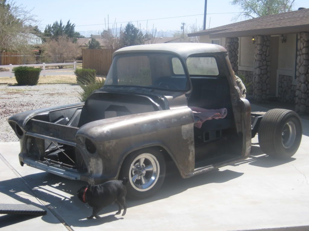
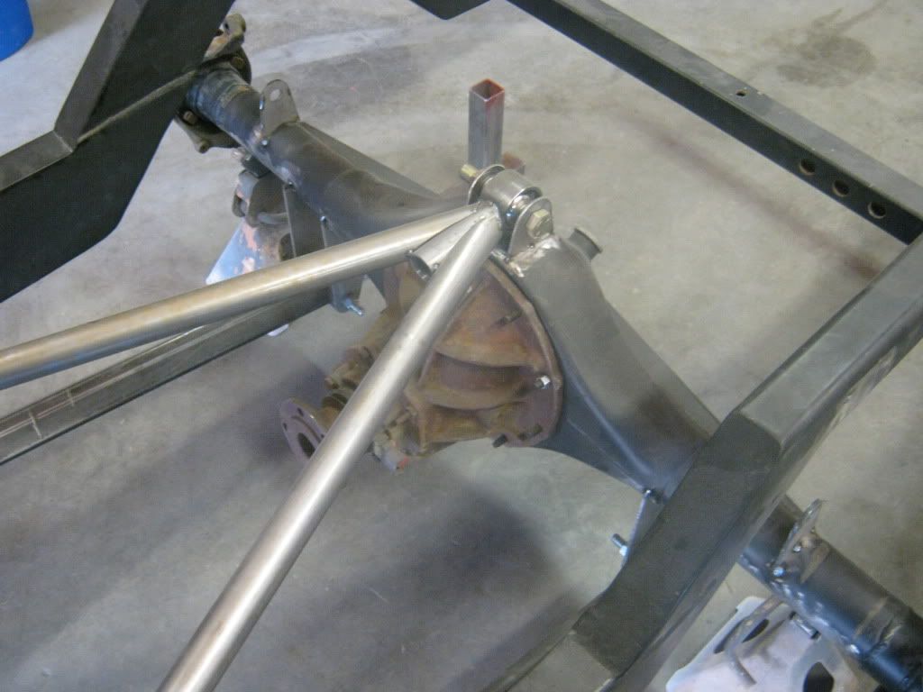
I got the forward and aft leaf spring brackets cut off and removed the fuel tank. Also, the original leaf spring perches have been cut off. Mike temporarily tacked the housing to the frame to simulate the highest point that the housing can travel in the upward direction. He had to do this to determine the max length of the lower bars. The housing will never go this high when it's completed because the rockers will hit the ground before the rear end ever gets to this point. Plus, I plan to have a small snubber just in case. Don't know why I'm wanting to do that, but I don't feel comfortable with a metal housing and a metal frame rail possibly making contact without a least some small kind of a buffer between them.
I took some pictures of the beast at the shop today. Mike is still hot and heavy on the dually because the owner added a bunch of extra stuff at the last minute. Here's a few shots of what he has done so far:
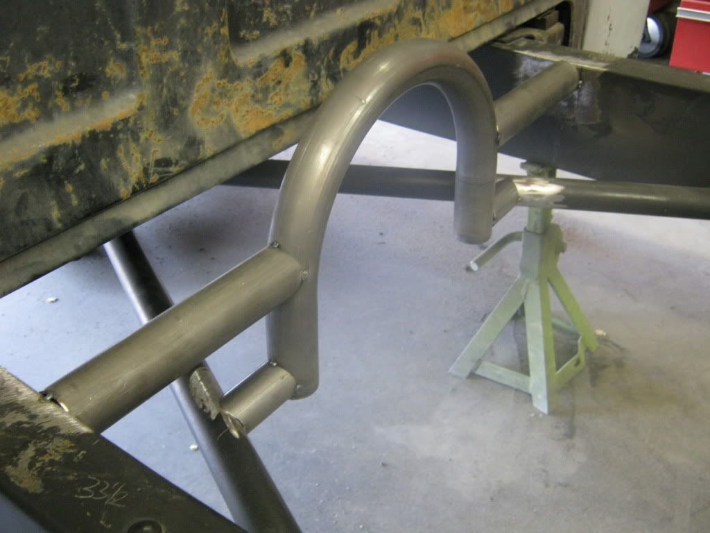
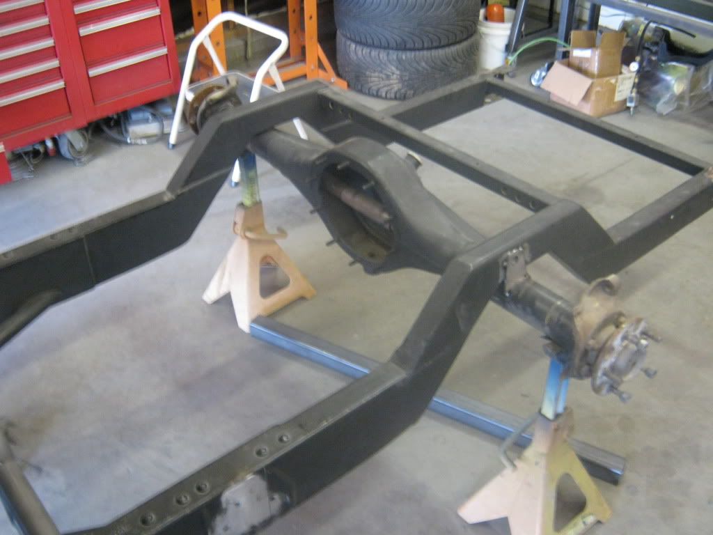
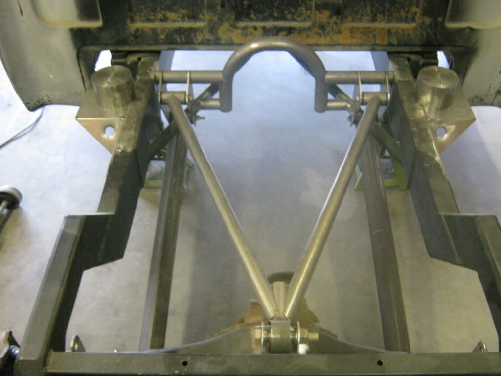
This is the beginning stages (just tacked welded in) of the support that will eventually have the forward attach points of the lower link bars and the upper bar. It is a 3-link set-up, so the upper bar will resemble a wishbone (2 attach points forward, 1 single attach point at the top side of the axle housing). He was able to attach the support to my X-member, so that'll tie everything together nicely. The frame is fully boxed with an x-member and all this extra tubing will ensure that my frame will NOT flex and should ride down the road nicely.
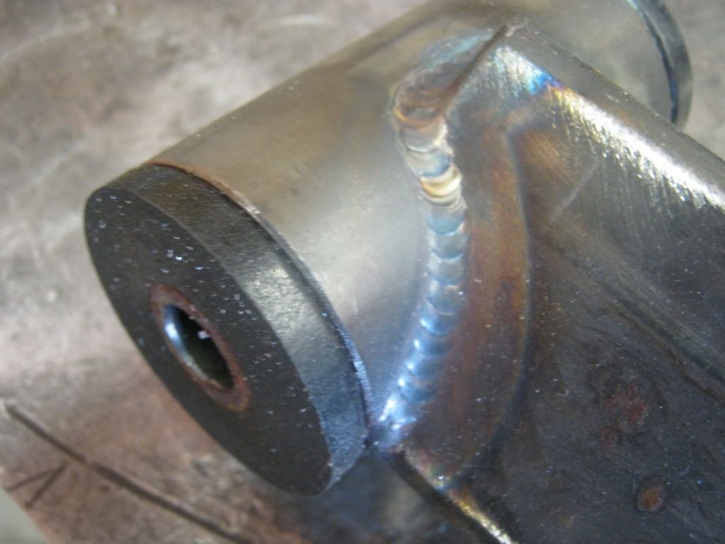
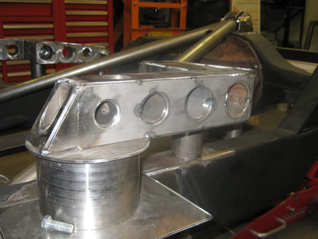
This is a shot of the one of the lower link bar ends. We decided to do a slightly different look and turn the 2"X2" lower tube on it's side and create a "diamond link". I thought I had a picture of the entire link but those are on my phone. Check out the welds. Nice, huh?
I was hoping to get the new SS series bags for the front and rear, but when the order showed up, the fronts were the SS bags and the rears were the RE bags. No problem, either version is a great product, so once the parts finally arrived, some work got accomplished. Here's few pictures I took today.
As you can see, everything so far is just tacked in place. The lower links and upper links are in and the system cycles really well.
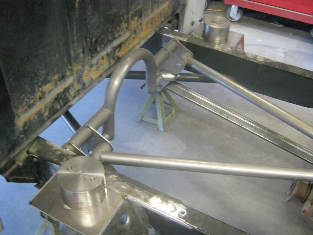
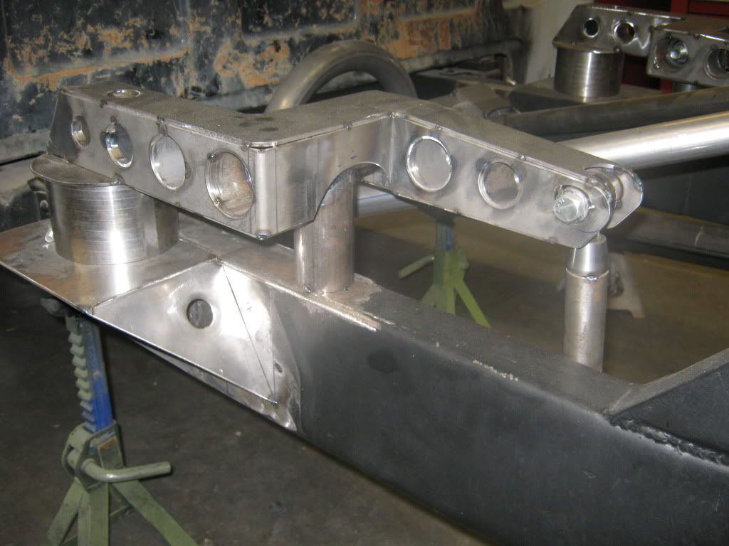
The forward brackets were a real challenge because of the existing x-member intersecting the attach points. Quite a bit of templates had to be made, but after some cutting and grinding, the brackets fit really well. They will be boxed and the flat areas will be dimple-died for a cool look. The bag mounts are tacked in, and the round piece of billet you see on top is a mock-up which simulates a deflated bag. That way, all of the measuring for any of the attach links is not based off of a floppy bag, but a solid piece.
The upper bar is still missing some gusseting, and the attach bracket will be boxed and plated for strength. All of the attach points you see in the pictures will be done that way. We decided to use a Uni-Ball instead of a heim at the attach point on the housing because it'll work great for articulation. There's still a ton of work to do, but these pictures will give you an idea of what the system will look like. Once the bag mounts are finished and the bell-cranks get built, along with all of the dimple-died plates, it'll look sick.
Mike had to finish a few projects ahead of mine before he could get going, so we're back on it. The guys at the shop that do the laser cutting messed up on some bracket patterns, so that slowed us up a bit. I made a few changes since the beginning, namely, more detail on the fabrication. I like the look of exposed, high quality TIG welds, and I like the look of lightening holes and feed-thrus. I want the design to meld with the functionality of the part. I don't like exposed things that look like an afterthought. Everything must flow, but still maintain it's functionality.
In an earlier post, I mentioned that the rear suspension is going to have bell-crank arms because of the limited space due to the truck being a step-side and also the fact that it has a narrowed rear end. I want the bags to be as far outboard as possible for stability. Here are some pictures of the progress:
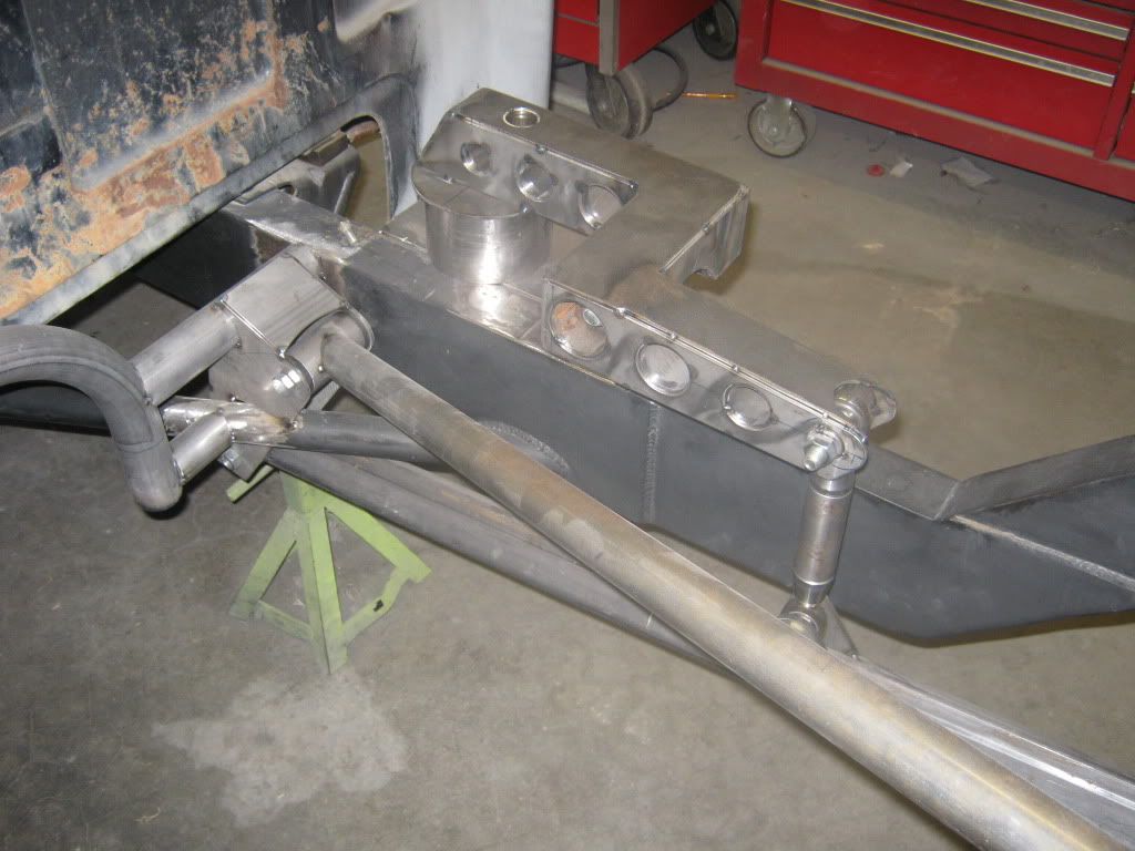
You can see the shape of the bell-crank in this shot. Currently, everything is tacked together until we get to a point where we're satisfied with the way it functions, then it will be final-welded. The link from the bell-crank to the lower trailing arm is chrome moly with welded-in rod end threaded bungs and the rod ends are the type they use on trophy trucks. They operate smoothly with no slop. The bolt for the pivot point is inside one of the lightening holes. There are still some gussets that will be added to the pivot point upright. The bushings at the pivot are the same as the ones from a trophy truck as well. The 6" round billet piece where the front of the bell-crank arm bolts to is an air-bag simulator, which simulates the air-bag at max deflation. Mike does not like using the bags during the fabrication stages because they can get damaged and they flex, which can be a problem if you're trying to get accurate measurements.
Close up shot of the arm. There will be gussets from the top of the framerail to the side of the pivot upright. Also, the relief cut-away will be opened up just a little more for additional clearance. We're still in the initial fabrication stage, so these things are normal and expected.
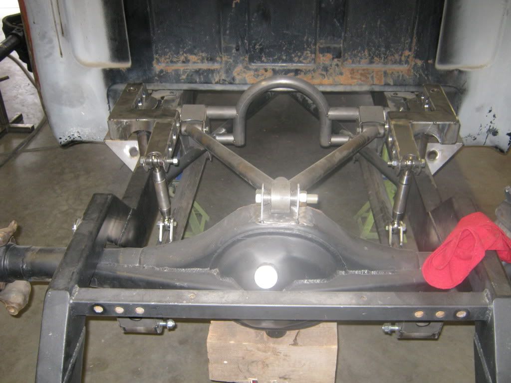
View from above. There's still alot of bridgework to do, shock mounts to make, figure out a swaybar set-up, and build the fuel tank, air tank mounts, compressor mounts, and battery box. The old shock crossmember will be cut out soon. It was staying in until the last because it was keeping the framerails parallel. I'm going to run out of room fast. We've got some ideas on packaging that will be very, very trick. Can't say right now, but the old saying about 10lbs of stuff in a 5 lb bag will be the idea.
Another shot of the air-bag simulator I was talking about. Bag bolt access will be gained through the tubes that you can see on the top of the arm. The bell-crank arm pivot bolt will be accessed through the tube (4th one from the left) on the right.
I'll keep posting when I get more pictures!!!