Meanwhile back at the ranch...
I put the engine/trans back in for the last-last time

I wasn't going to until it's painted but I came to the conclusion that verifying the strut braces clear the engine before welding them up, and fitting the exhaust might not be a bad idea.
So the engine is in again. The big brown truck of gifts dropped this off:

Mine's actually the DBX series. They've been changing the name...
That naturally led me to look at where it's going to fit under the car. Looks like there's a good spot under the rear seat pan.
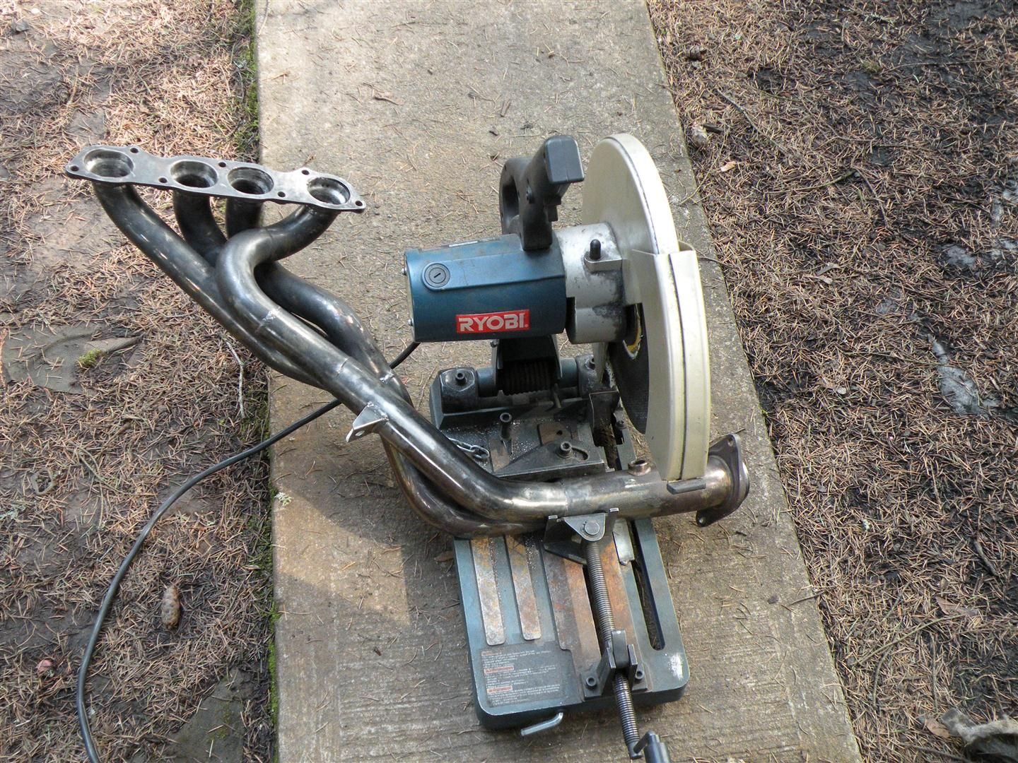
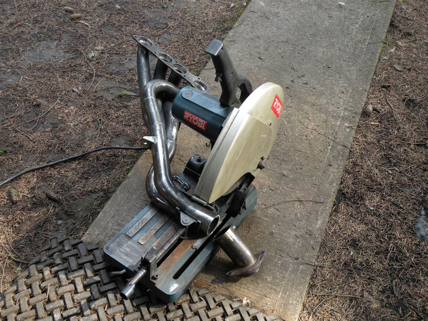
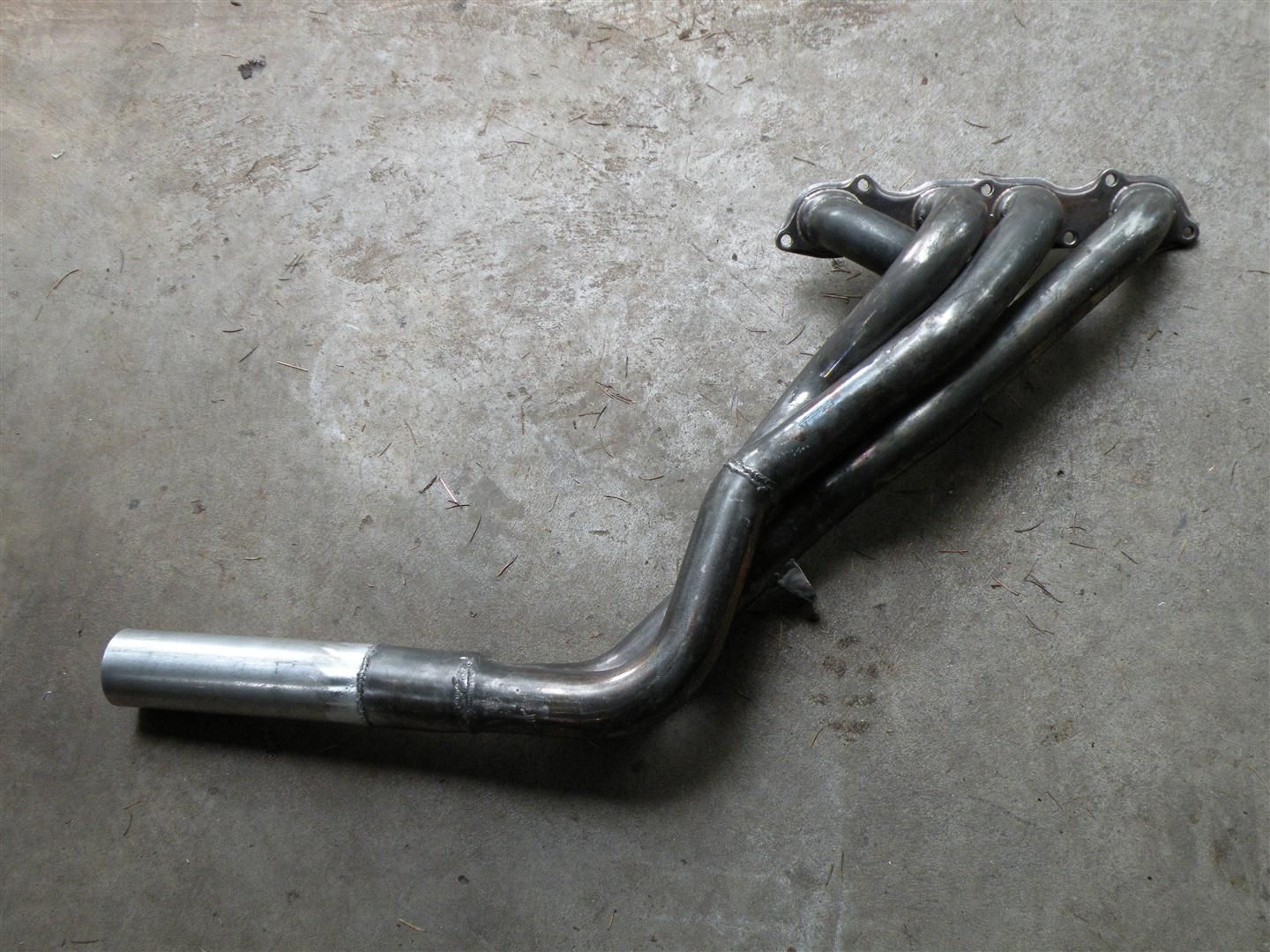
Of course, in order to determine the precise position the rest of the pipes need to be mocked up; starting with the header.
Over the years I've read engine building and tuning books, including a few by David Vizard.
This article sums up the exhaust tuning theory pretty well.
Based on the fact that the collector dimensions are as critical as (and some say more critical than) the primaries, I will attempt to build the exhaust system according to those principles as best as I can.
Doing so will consist of three things:
- Collector sized correctly for this engine/peak power range
- A wave termination chamber (to simulate atmosphere)
- As little restriction as possible past that point (while still quieting it down)
What's a wave termination chamber? It's a chamber/box at least 8x the volume of one cylinder that effectively causes a negative pressure pulse wave to be generated by the change in volume (collector to atm. or collector to wave termination box). The negative pressure wave travels back up the header, and if tuned correctly, will arrive at the exhaust valve at just the right time (per tuned RPM) to scavenge the cylinder and "suck" the next intake charge into the cylinder.
Here's what the chamber might look like:

But before I can terminate the wave, I need the "optimal" collector dimensions. Short of finding that on a dyno, there are some pretty well established constants/factors/relationships (lot's of math and experience) put together into formulas. Bottom line, more than I'd prefer to research and calculate. That's where a good software program pays for itself. I went with
Pipemax Header Design Software.
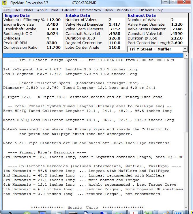
Here's what it spit out for a stock F20C with a street Tri-Y header:
[IMG]
[/IMG]
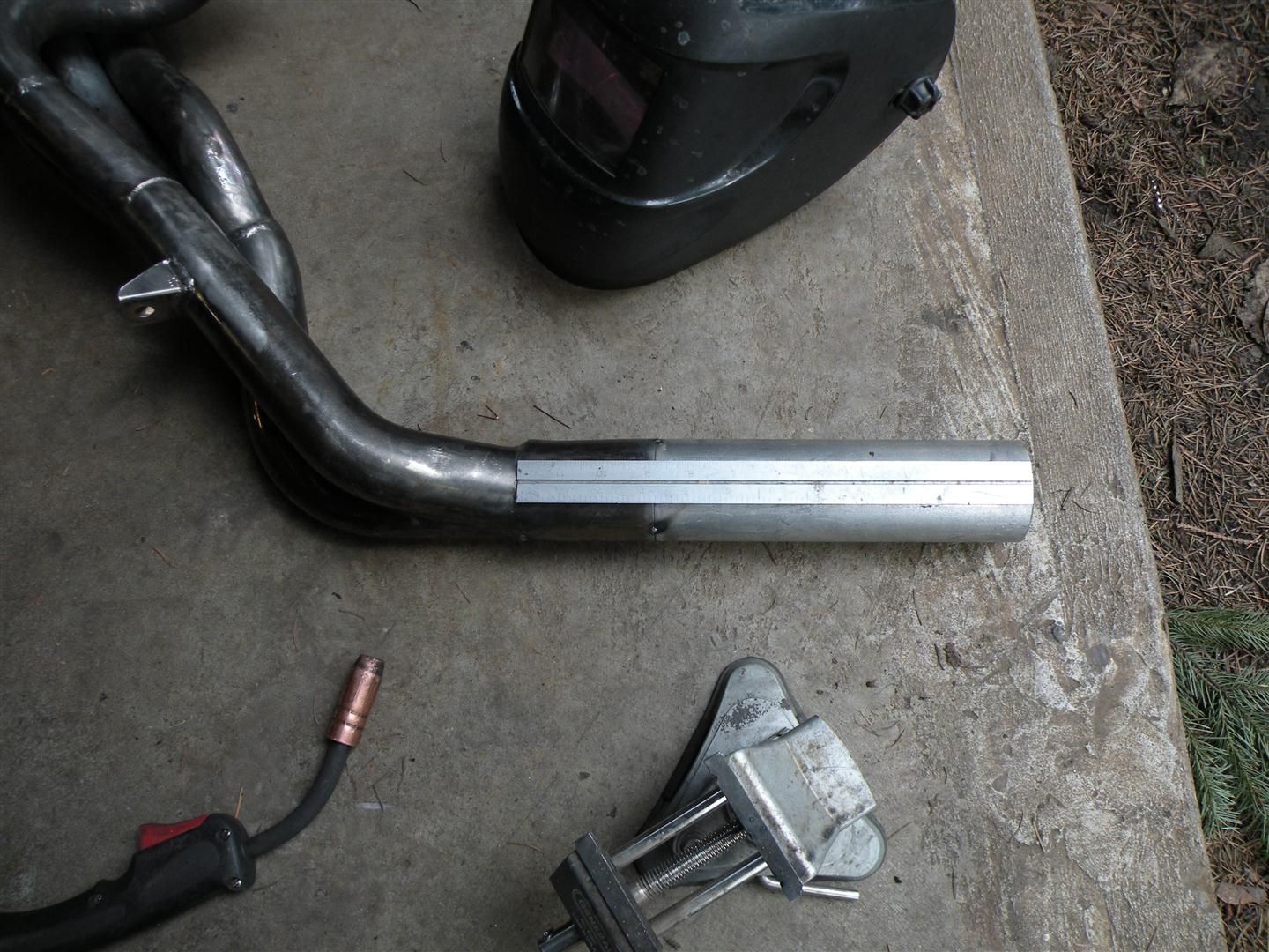
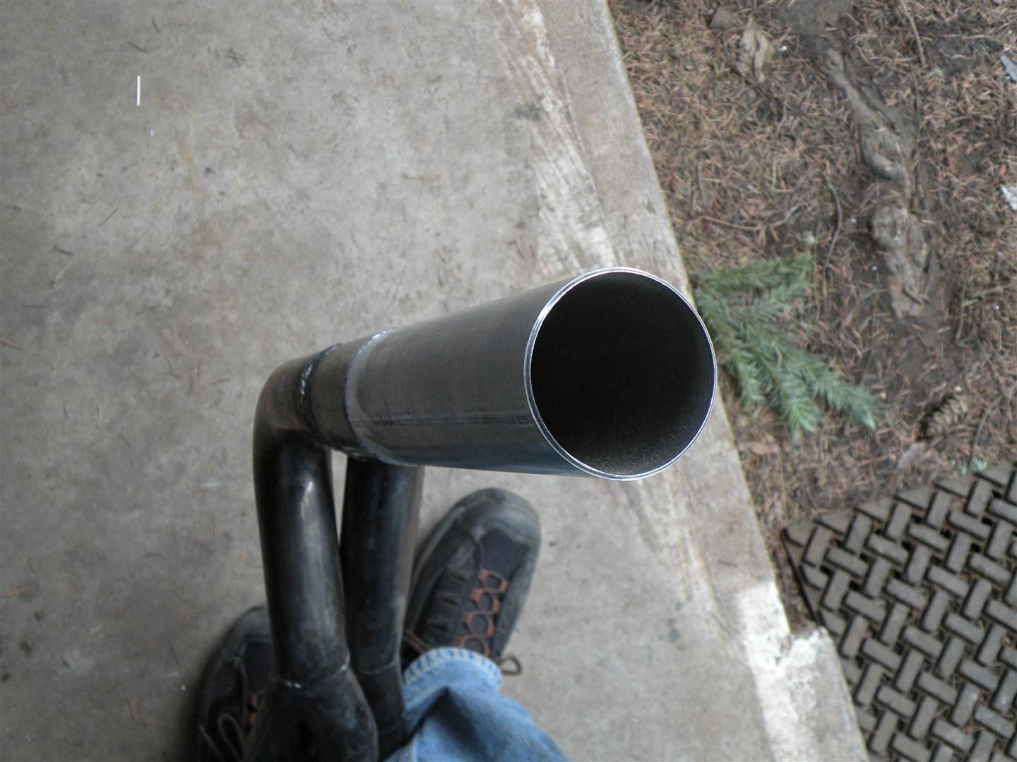
So given that I (luckily) already have a 2.5" collector, now I just need to make it ~12.1" long:
More to come...