|
Re: Alternator Wiring
......
Quote:
Originally Posted by truckster

Just to be clear, because I also have the single brown wire on the alternator that's going into my 72 Blazer, together with a new wiring harness: I should put a resistor between the brown wire and the wire that's labeled Alternator Exciter. I think I understand that part.
But you said that for better voltage sensing the output terminal should be wired to the fuse panel and not directly to the battery or starter post. My wiring kit says to run a bypass wire if using an alternator with higher than 80 amp capacity. So if I run a bypass wire, my voltage gauge (which replaced my ammeter) will still read voltage but might not be exactly right. Did I get that right, or am I missing something?
You'll need the resistor in the place you noted.
You should run a larger gauge output wire from the alternator to the main junction usually not the fuse panel. See pic below. I don't think the voltmeter will be affected. You can check it with a voltmeter at the alternator and the battery for comparison.
And I realize I'm somewhat hijacking a thread, but I suspect Wade might run into the same type of issue.
Thanks
David
|
Quote:
Originally Posted by Driver_WT
Thank you VetteVet for the very detailed response. Can you enlighten me a bit more on what is considered a "main junction". My current wiring harness diagram says to run the alternator output wire to the large terminal on the starter solenoid and the main feed for my new wiring harness also runs from the large terminal on the starter solenoid to the fuse box.
Wade
|
If you are taking your power feed off the battery cable at the starter solenoid it might be considered a main junction. The best way would be to run the alternator output wire ( 8 gauge ) to the main junction like shown below, however your way will work.It's kinda the same thing.
Notice the sensing wire and the alternator output wire are run to the same spot on the main junction. This one uses a 10 SI alternator so it needs the sensing wire whereas the CS 130 one wire does not. Also the output wire is 4 gauge
which is overkill but this diagram uses a rear mounted battery so maybe they think they need that large of wire.
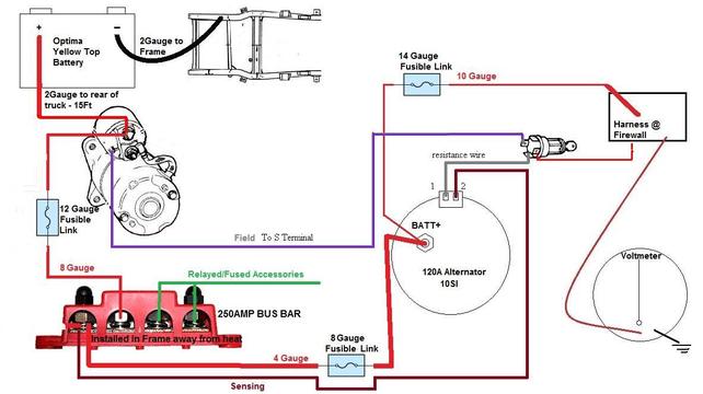
This method will not allow the original battery meter AKA ammeter to work so if one needs to have that function the wiring must be different. I would need a different thread to detail that.
__________________
VetteVet
metallic green 67 stepside
74 corvette convertible
1965 Harley sportster
1995 Harley wide glide
Growing old is hell, but it beats the alternative.
|