I liked the API-4260-LW150-R programmable buzzer so well I added another one. These days, flashers do not make an adequately loud tink-tonk for me to hear, especially over the unnecessarily-loud exhaust. So I programmed it to make a loud tink-tonk by shopping for sounds on freesound.org and liked this one
https://freesound.org/people/ermine/sounds/23968/
I reduced noise and amplified the sound with
Audacity and uploaded it into the buzzer with the PUI Indicator software like I did in my earlier post for the headlight warning.
For a couple months I connected it directly to the terminals of the flasher module and it played a very short sound. That was OK, but it would only play the tink and not the tonk.
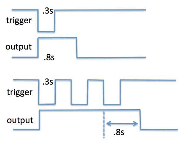
So, I made a little circuit to turn the on-off-on-off blink voltage into a constant on voltage, that is on while the blinker is on. I used a 555 timer chip set up as a retriggerable monostable multivibrator with a diode to drain the capacitor and start the timer over each time the flasher module blinked the bulbs.
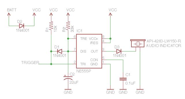
I designed the schematic and used a calculator for the capacitor and resistor values.
http://www.ohmslawcalculator.com/555...ble-calculator Diode D1 is to discharge the capacitor and start the timer over, so the buzzer will turn off a little while after the last blink. The other diodes are optional and just for reverse polarity protection, so I don't burn anything out if I hook it up wrong.
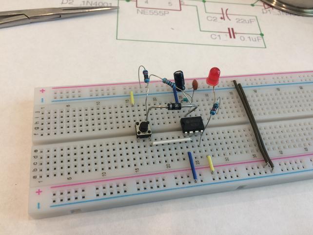
I prototyped it and connected it to the truck to make sure it would work.
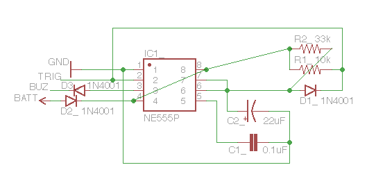
I rearranged the schematic to visualize the best layout of the parts on the circuit board.
I glued the components down with a little daub of E-6000 glue and soldered it together.
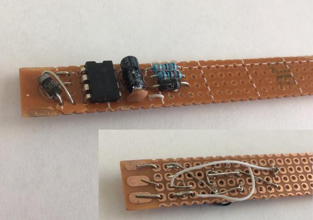
The battery voltage input for the circuit comes from the top connector of the flasher, the trigger input comes from the bottom connector of the flasher, and ground comes from a bare metal screw under the dash. I soldered directly to the flasher pins with thin wire. After assembling the 555 timer module, I encased it with heat shrink tubing and glued it to the buzzer. I used a zip-tie to hang it by one of its mounting ears to the wire bundle just like I did for the headlight warning buzzer as shown in my earlier post.
I can change the sound using a USB cable and computer if I want. It is possible to upload any sound that will remind me to turn off the blinker. I could program it for 25 seconds of silence followed by a brief boop or voice reminder "blinker is on" or something like that, or use a song snippet. The buzzer allows up to a 30 second sound to be uploaded, and it repeats the sound. For now I'm just going to use the tink-tonk sound.