Mike is still plugging away on the Drummer's Lounge sign.
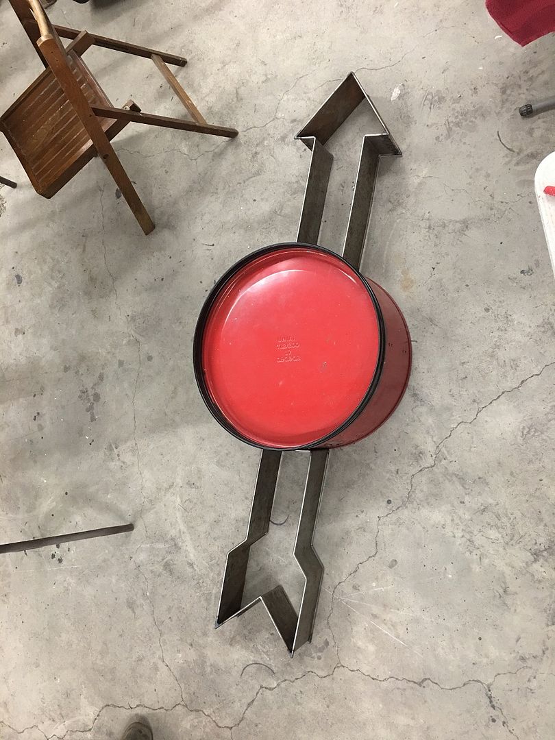
Saturday he started fabrication of the insert panels. One side will be plug welded in place, the other will be removeable to access the wiring for the flashing lights.
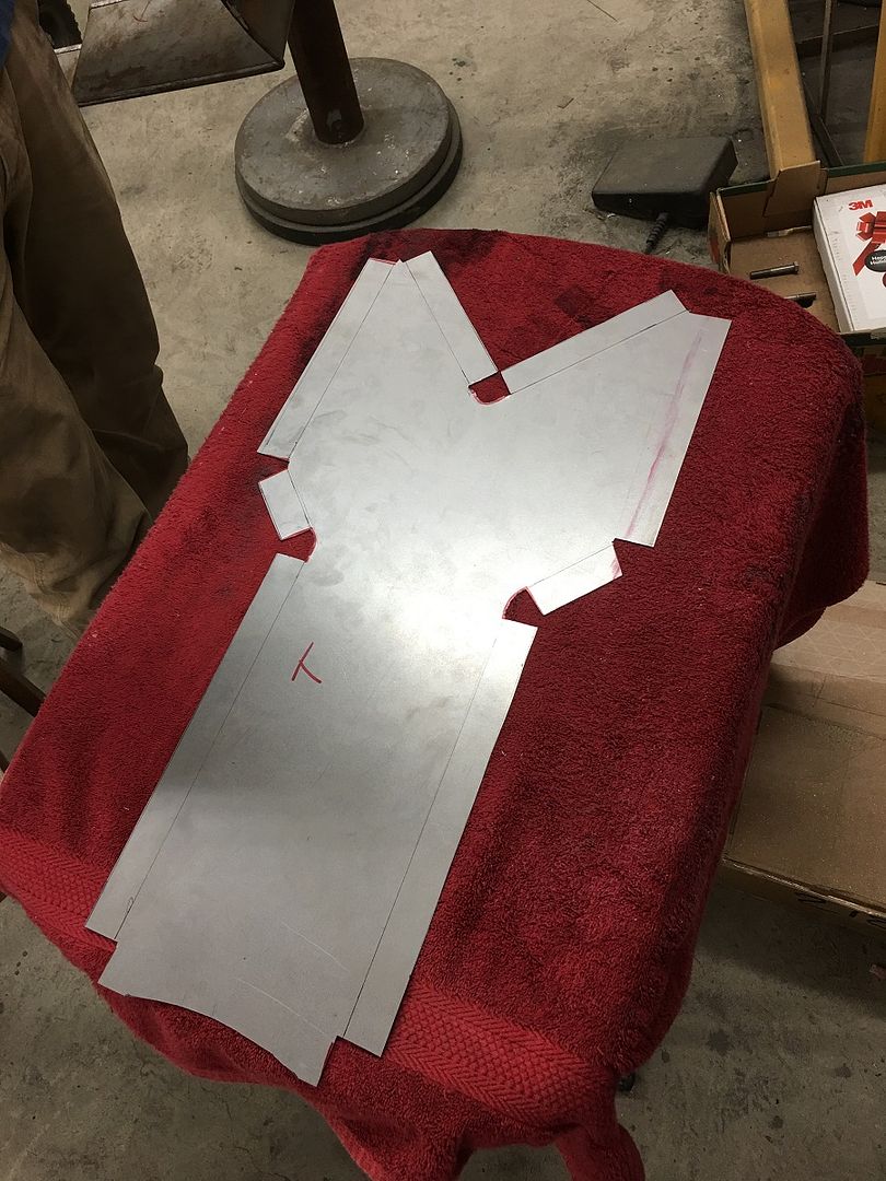
Tracing the first pattern onto some 19 ga crs, and adding mounting flanges.
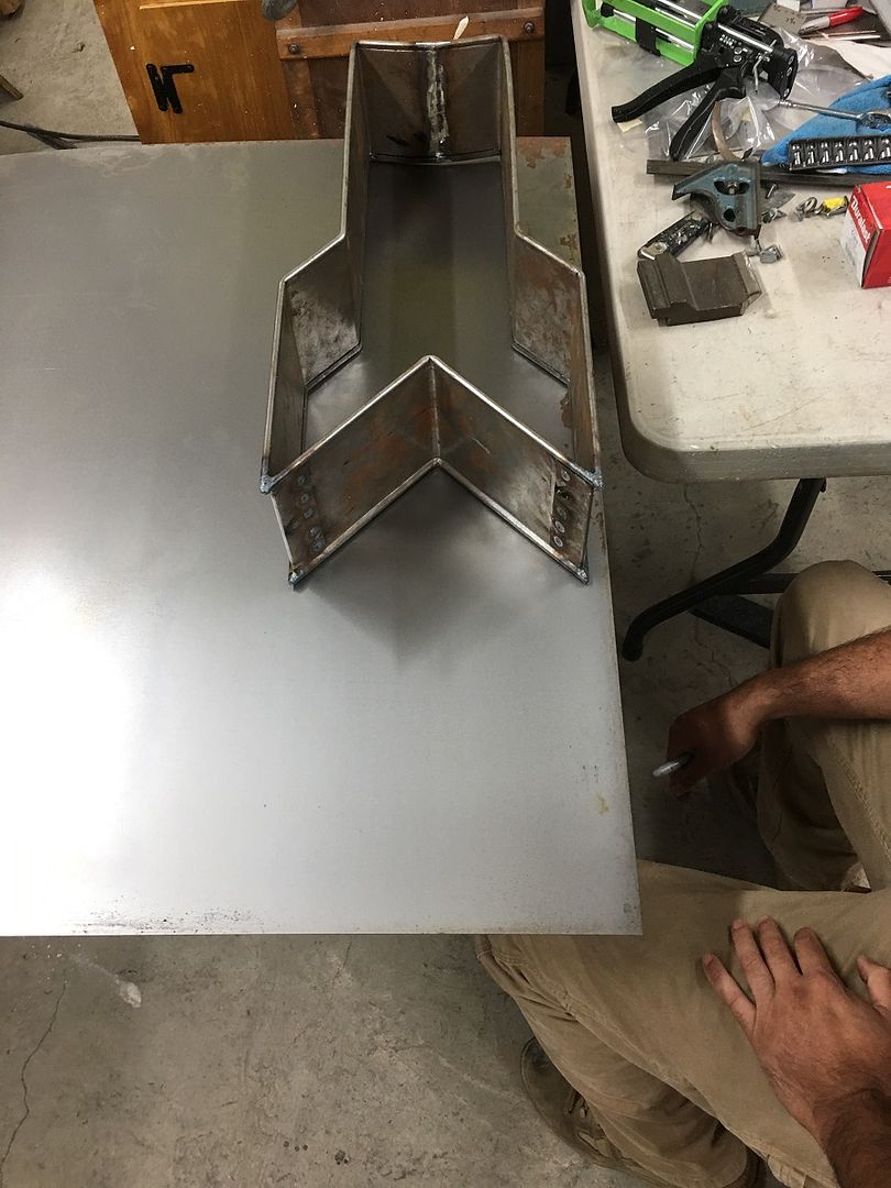
The bend lines are run through the bead roller with a tipping die into the skate board wheel to better mark the bend location. Makes it easier to locate the upper press brake die as it will fall into the indent.
Since everything is a tool, and we needed to fold down a bit of metal in the inside corner, a piece of angle is chosen for it's inside radius match and a body hammer with a nice barrel roll on it does the trick...
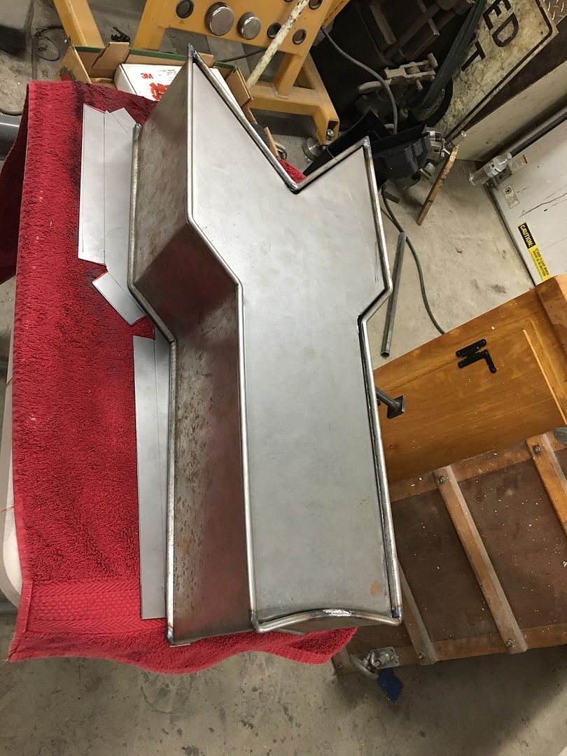
Side #2....
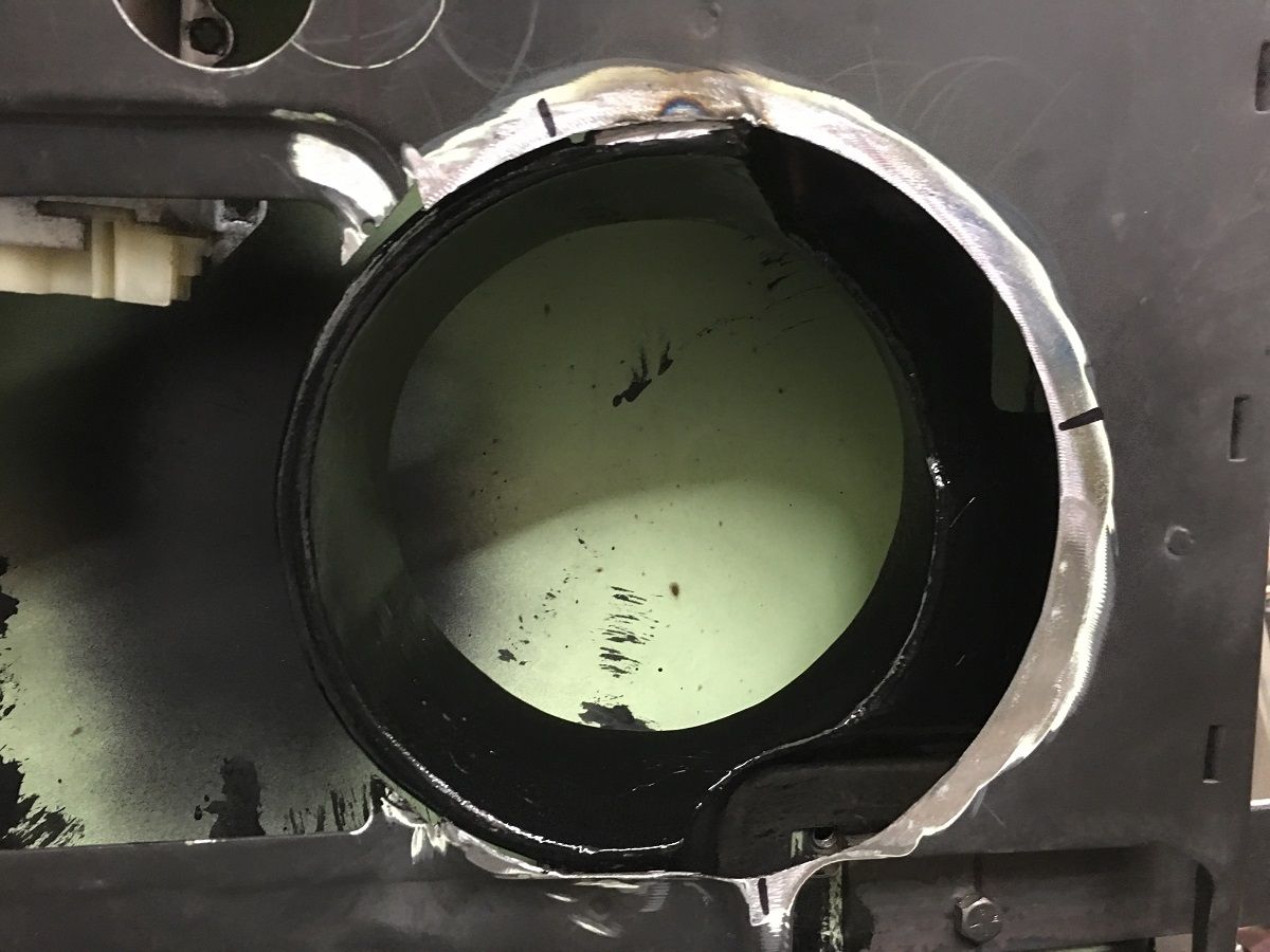
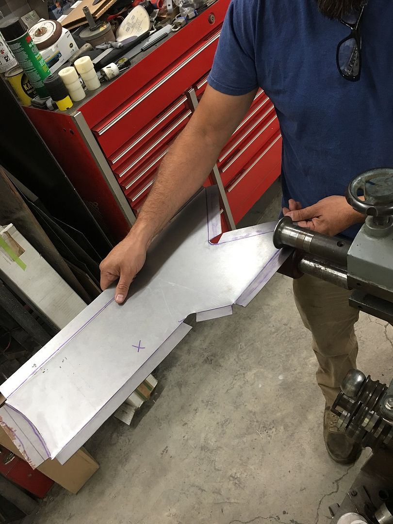
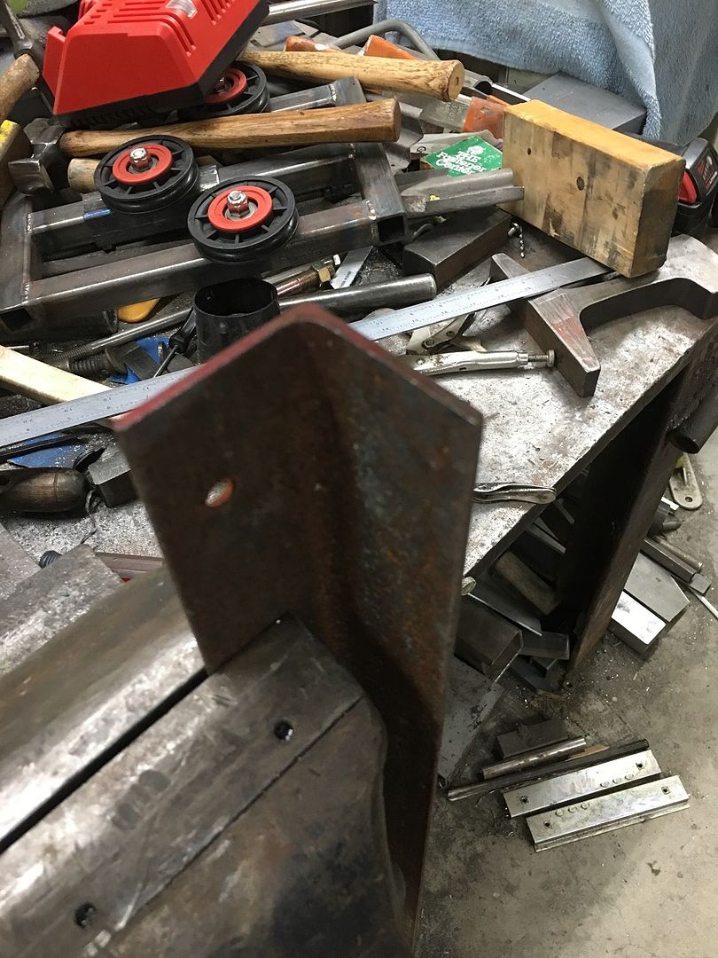
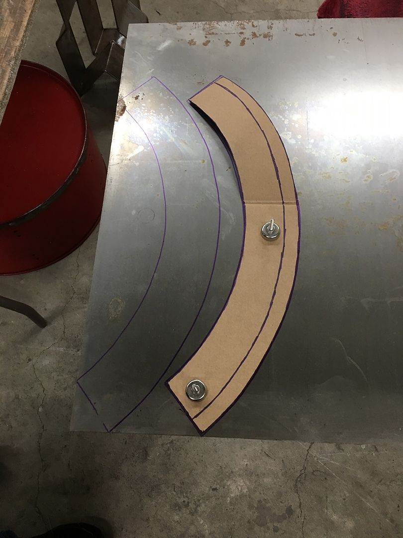
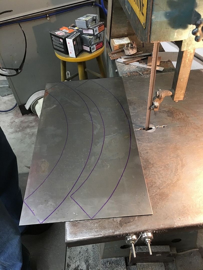
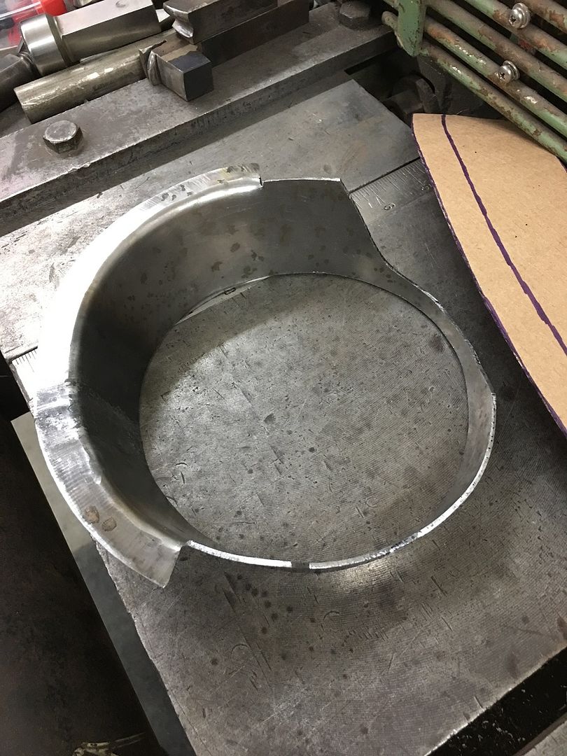
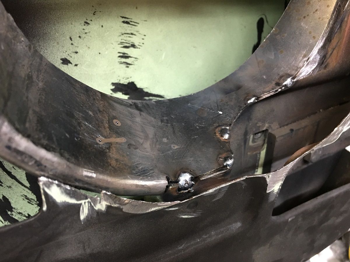
While he was busy with that, I continued on our speaker mount modification to the doors. Since we had cut away at the hinge mounting structure, we needed to add strength back in that surrounded the speaker. We chose a cone shape over cylindrical as we thought that would have less chance of collapse under stress. Our pattern is cut out and transferred to some 14 gauge cold rolled, the same thickness as the hinge structure.
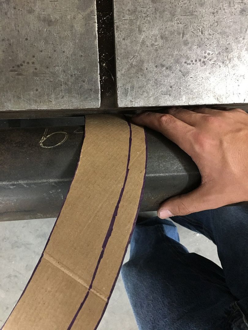
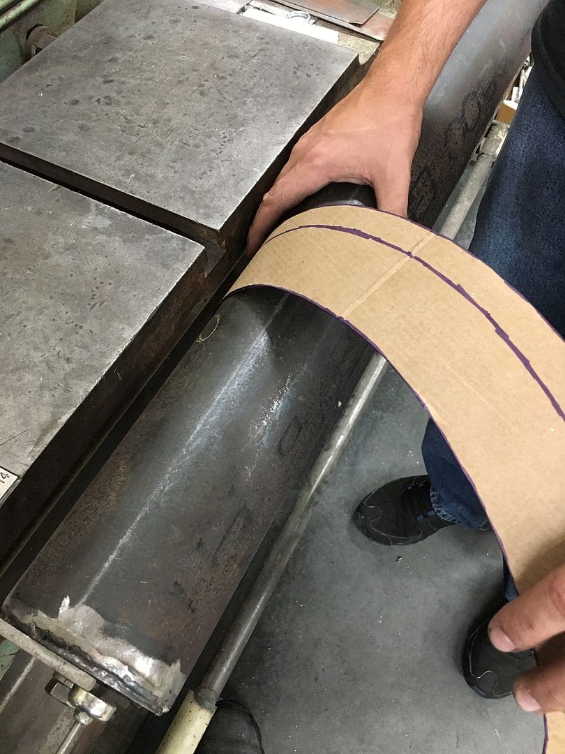
I forgot to get pictures of us rolling the cones, but basically as shown here with the pattern, the bend line was kept aligned with the vertex of the outer angle cuts, and slightly pressed, move and repeat, and continued until we have a good roll where the ends met up.
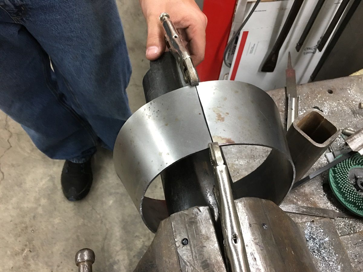
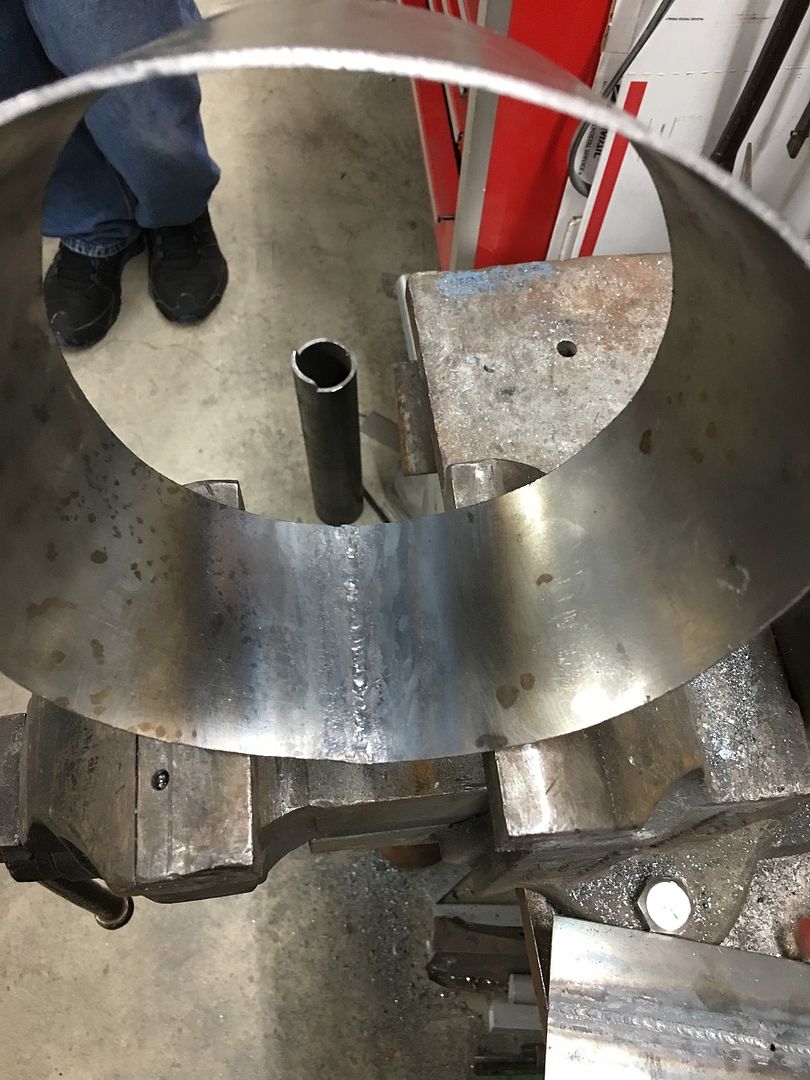
We plan on wire edge on the edge inside the square opening, so let's use gas welding for a more pliable weld area.
 https://www.youtube.com/watch?v=hEWXNOFgSas
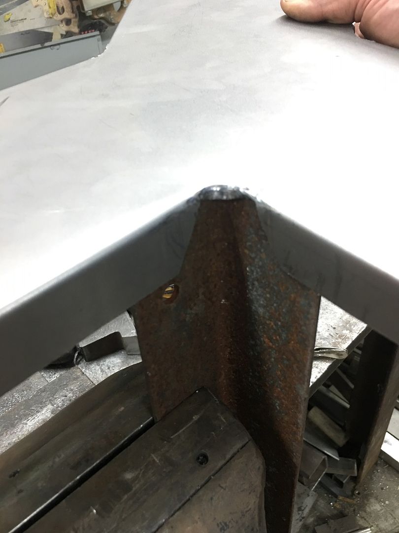
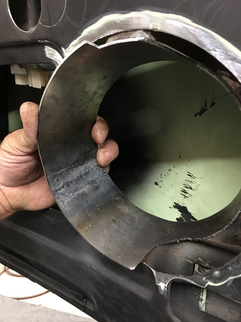
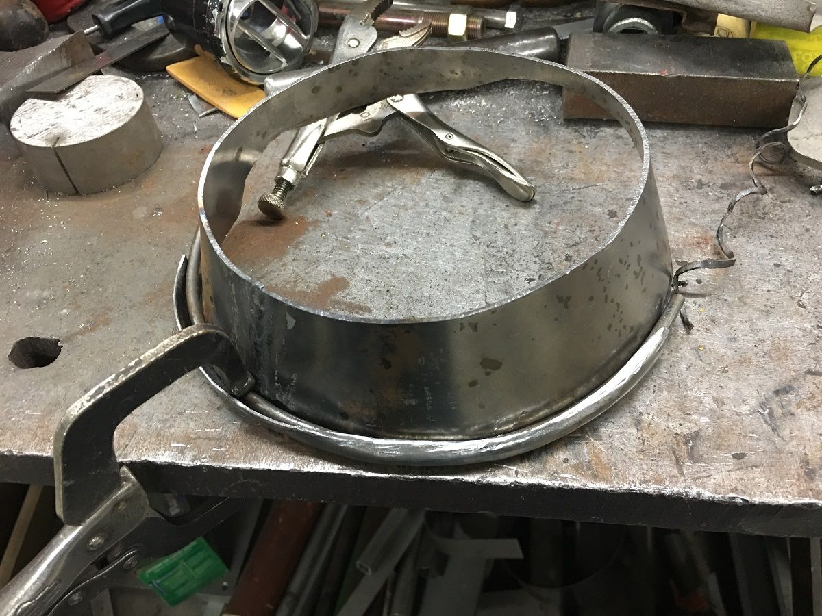
The cone is then trimmed to fit the structure profile...
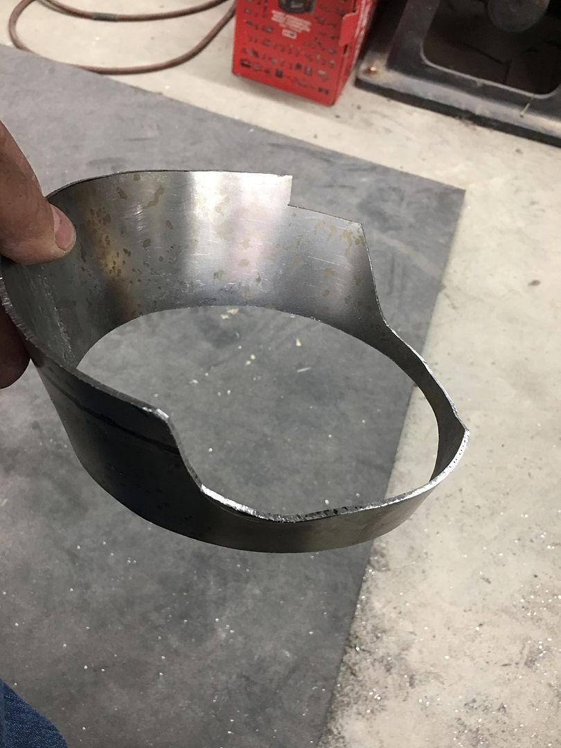

Flange is left for our wire edging of the open area...
The flange is tipped on the bead roller and then used the linear stretch dies in the Lennox to both stretch and tip the flange over to flat.
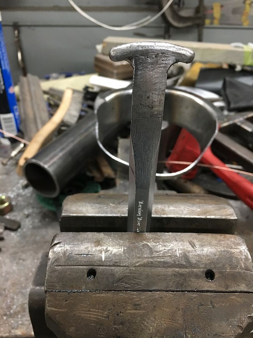
Then we use this modified Craftsman punch to hammer over a rounded void for the 3/16 wire to lay in..
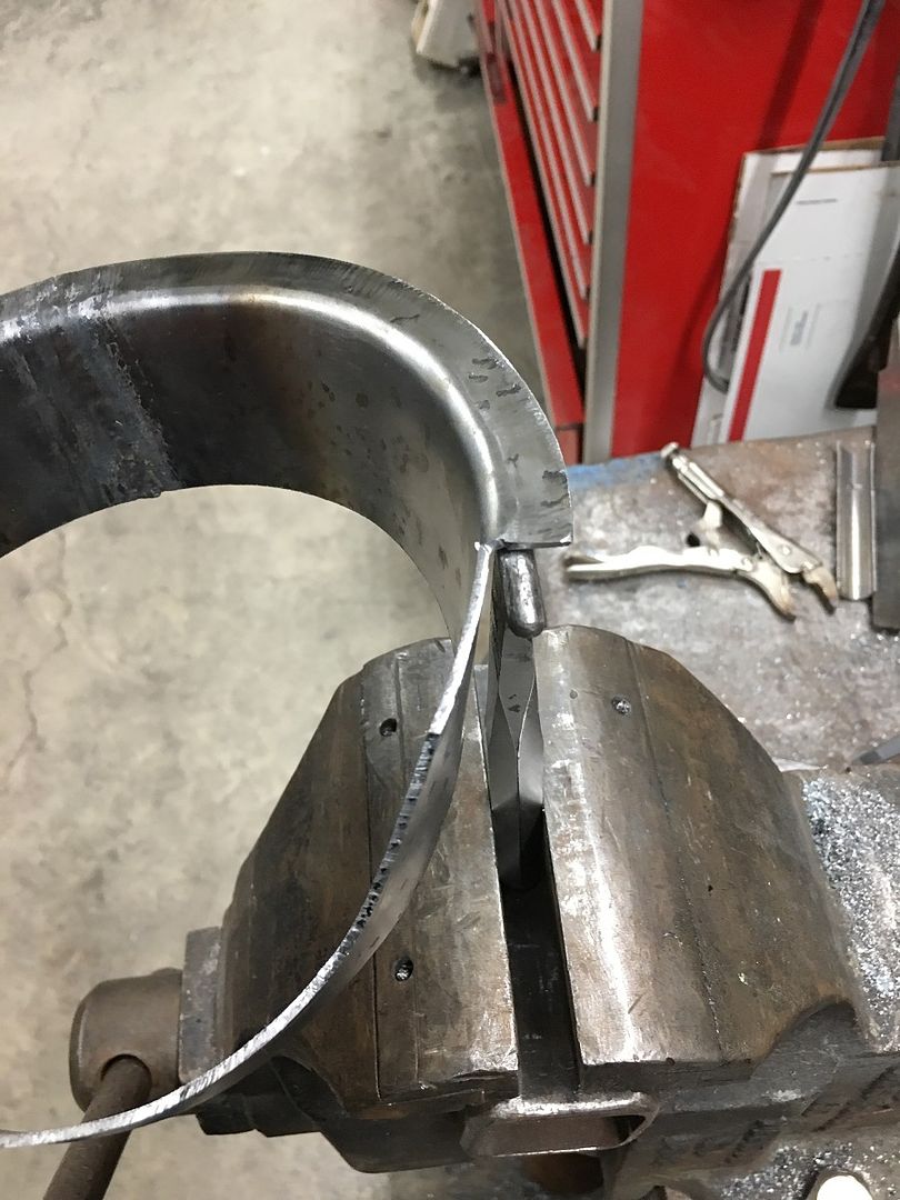
Then we have some modified vise grips that have a relief cut into the top so it won't slip off the wire when clamped.
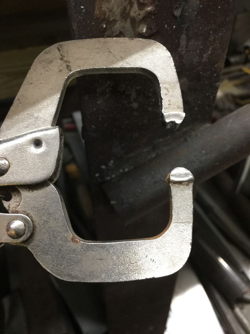
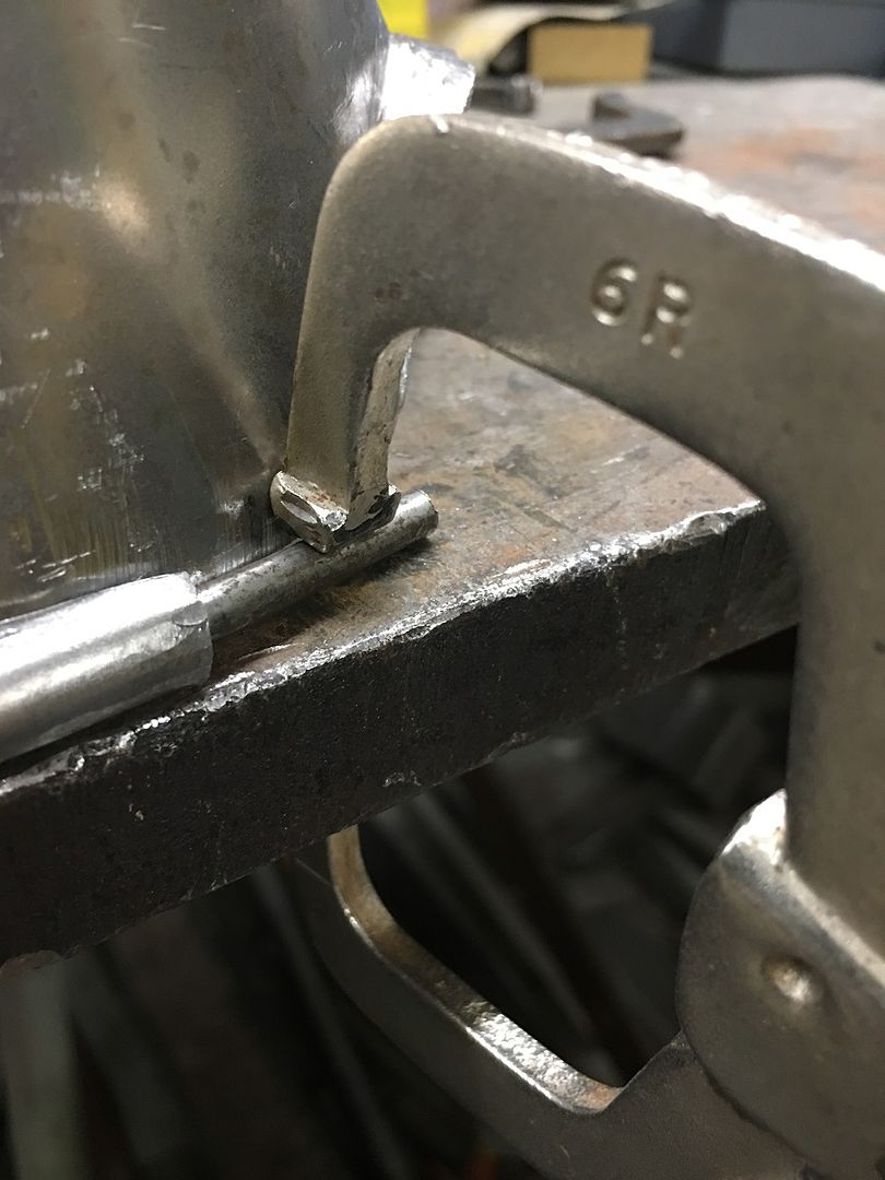
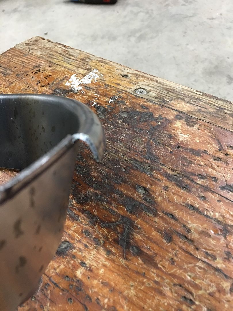
The wires were left long so they could better tie into the hinge structure, here the VEE relief is where the wire will weld to that structure.
https://www.youtube.com/watch?v=mEVDpRCER54
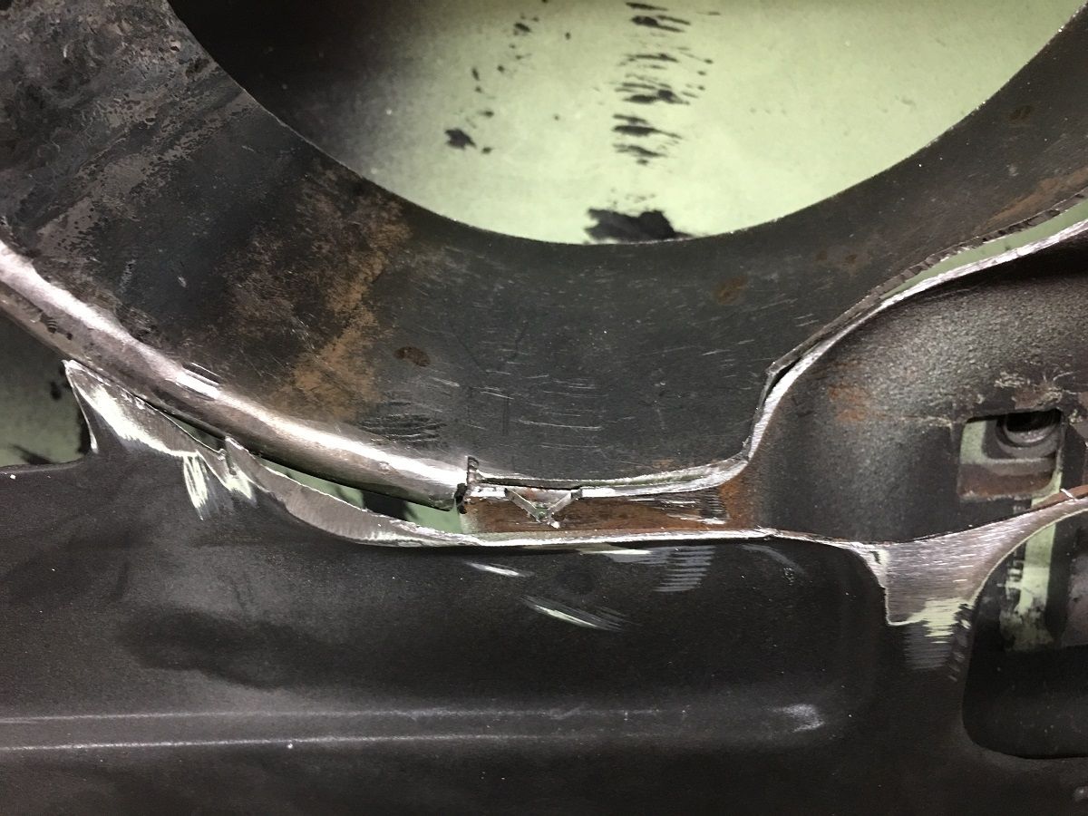
Tacked in place with the MIG, then TIG welded....
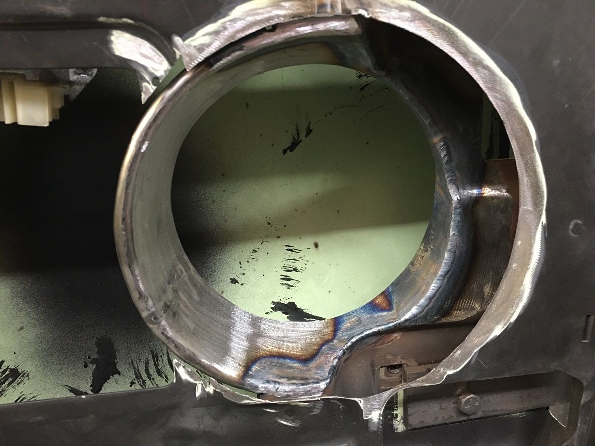
All cleaned up and then primed with some epoxy primer before we weld the speaker mounting ring in place.