Little project I'm playing with. I forget what gauge I started from, oil or temp...
Goal is to get canbus data to drive the gauge, but right now its just analog input / sensor input
I removed the old sending unit, measured center to center, measured the stepper motor, modeled it in cad and 3d printed an adapter. Took 2 tries to get the alignment 100%, pretty impressed with that!
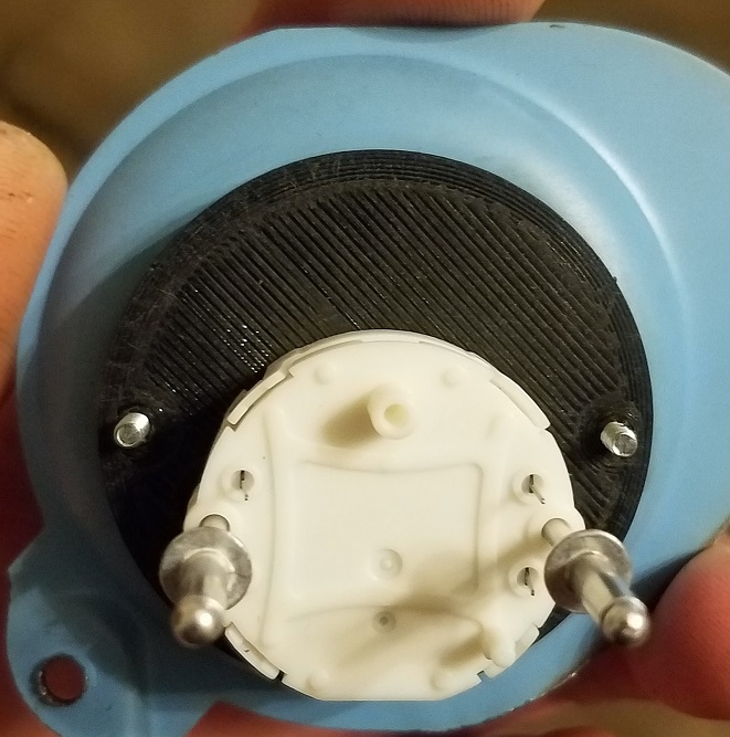
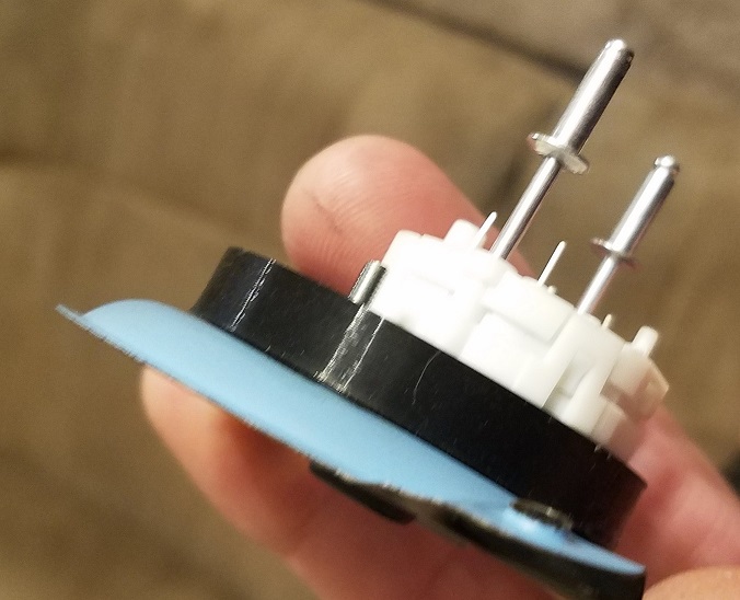
I didn't have any more tiny screws on hand, but a rivet had the right diameter.... alignment on point!
I had some prototype circuit board from a previous project and its hole spacing was perfect for the back of the stepper motor... I cut the circuit board to fit, soldered leads to it and finally to the stepper motor... the leads on the stepper motor are very thin gauge and I think would get damaged if I just soldered wires to the back of them. Being they are designed to be soldered to a circuit board.. lets go that route

I did some searching and found some librarys to control the stepper motor and started basic and then expanded... that turned into lots of coding attempts, many hours later and here I am... kinda close to the end of this part ... still need to figure out a few things but pretty cool none the less (to me at least)...
Video showing function test:
Set to a value using the potentiometer, pressed reset as if you turned key on, or restarted truck... gauge resets and goes to current value. Turn knob to end stops, press reset and gauge returns to current value.
short video using potentiometer to drive gauge
Got the gauge code configurable:
so the gauge needle sweep aligns with tick marks on the face
there's an offset so if operating temp is not exactly at 1/2 on the gauge, it can be adjusted so its more visually appealing while still maintaining the 90º sweep
sensor start range for coolant temp sensor
pretty crazy stuff you can do with an arduino nano , stepper motor driver board, stepper motor and many hours
clint