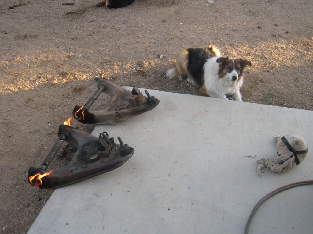
I was able to get on the truck for a few hours yesterday. It was really cold and windy, so that kept me from getting a whole lot done. I was able to drive out the lower control arm bushings with the air chisel, and while the lower control arm cross shafts were out, I blasted them clean.
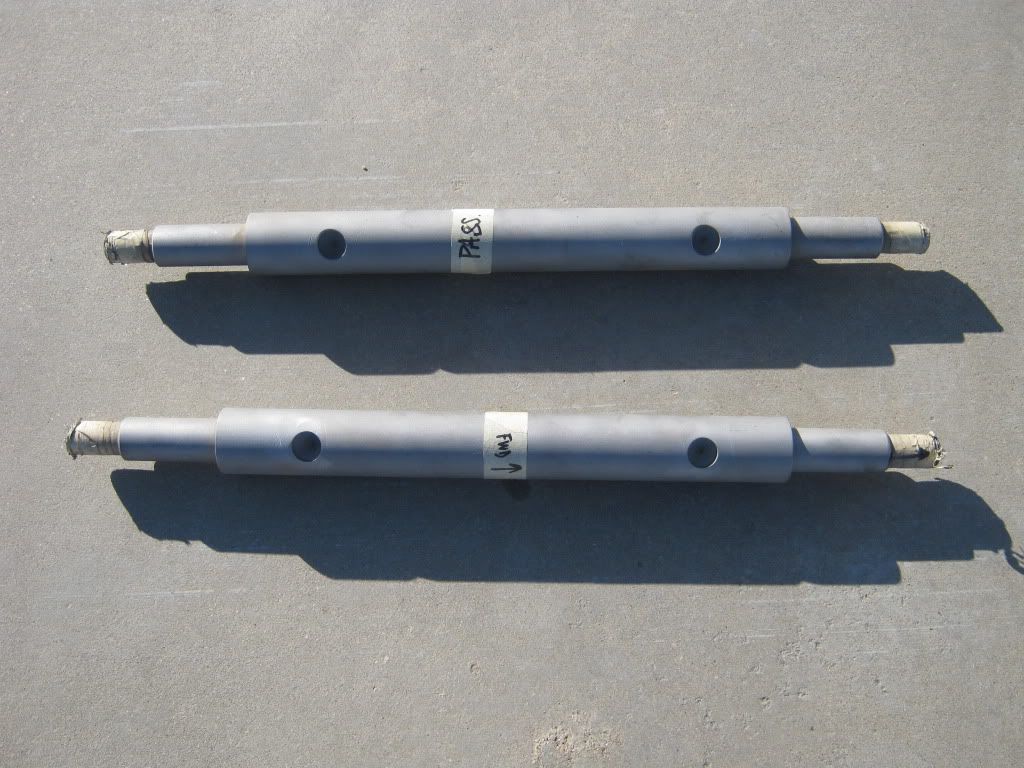
I am working on a mod to increase caster, so these cross shafts are going to a buddy's house so they can be machined. The intent is to move the lower control arm forward .75", thus tilting the spindle back, increasing caster. The machining will be very simple. Here's a quick drawing I did on Powerpoint to show you what I am going to do:

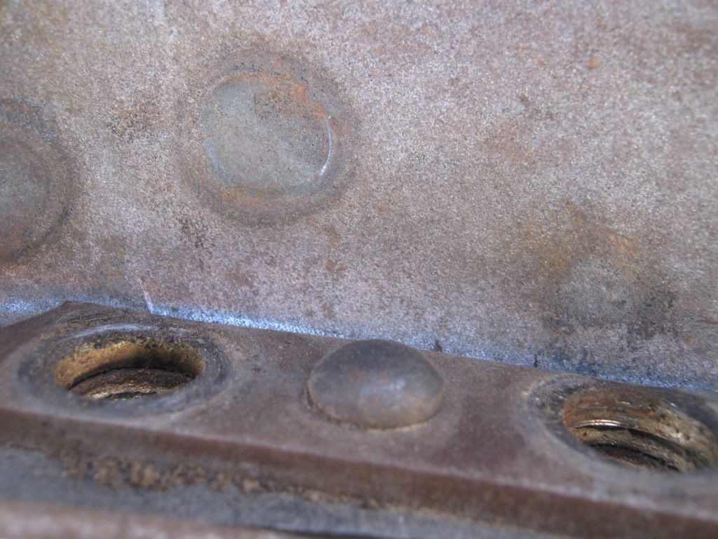
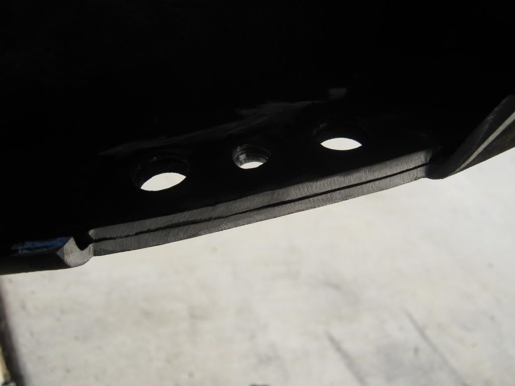
In order to do this mod, you have to remove the saddles that are riveted to the center crossmember. There are four of them, two on each side. These saddles are what keeps the lower control arm in position, and are held in place with u-bolts. They are kept from spinning by a stud that locates itself in the spot-faced holes in the lower control arm shaft. Here, you can see a picture of the front crossmember showing the two bolt holes for the u-bolts and the rivet head for the locating stud I mentioned earlier. The stud side is not visible in this picture.
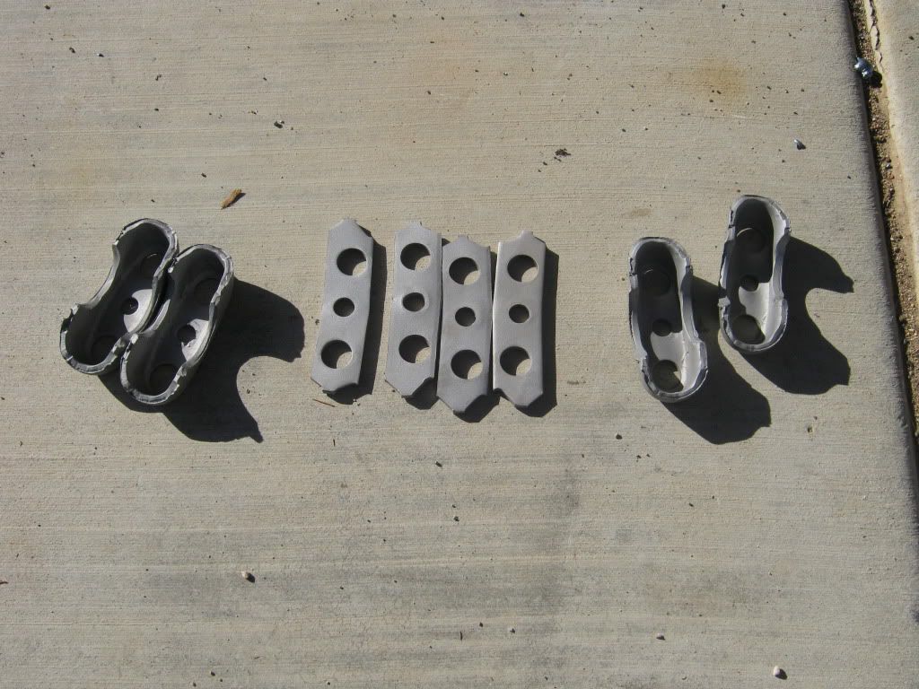
In order to get the saddles removed, you have a few options. You can grind the heads off and drive out the rest of the rivet. Or, you can fire up the torch and melt the rivet heads off, then drive out the rest. I opted for the torch. I learned quickly that even with the head and tail of the rivet melted off, the rivet stems did not come out without a fight. I had to warm up the rivet stem with the torch and shoot them out with an air chisel. The rivets go through 4 layers of steel (doubler plate, saddle, and and 2 layers crossmember). Once you get them out, here's what the pieces look like after a few minutes in the blaster:
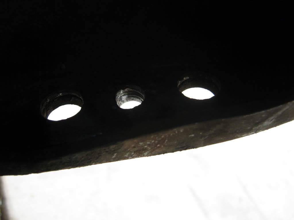
Here's what you'll see when the saddles, doubler, and rivets are removed. I decided that I was going to use a 7/16 X 1.25 socket head cap screw as the new locating pin, so the center hole in this picture needed to get opened up to a 7/16 to ensure that bolt would fit nice and tight. The light area in the front is the lip on the crossmember, which will be cut away. Sorry for the dark picture, my lighting was a little goofy yesterday.
Moving the control arm forward will cause the aft side of the control arm to get really close to the center crossmember, so I removed the lip and blended out the cut to eliminate any sharp edges that could cause a stress riser. You will only need to cut the lip back to where it meets the second metal layer.
That's all I got done yesterday. After the shafts get machined, I put them in place and show you the difference.
I promised earlier to show you a funny picture of the Border Collie, Tori. I was burning out the old control arm bushings and she was right in the smoke path, but she was so focused on wanting to play fetch she was oblivious to what was going on. She lives to play fetch. I'll be working underneath the truck and she'll constantly drop her stick or her ball right on your foot to get your attention. Goofball........
More to come!!!!