Here's some dimensions.
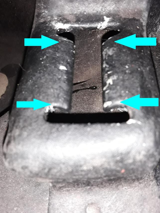
Between each set of blue arrows is 0.38 - that's the width of the slot
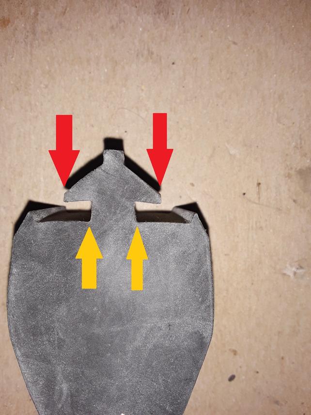
Here's a side view of the bumper. Dimension between the 2 yellow arrows is about 0.36 . So once installed it's about as snug as can be.
Dimension between the 2 red arrows is just about 0.80 . Obviously it can't go straight through the slot, one side will have to be inserted first, then the other.
The thing that's really getting me is I took a straight edge across the top of the bracket, say between two opposing blue arrows. I took another flat surface across the bottom of those 2 tabs where they are bent down. The vertical difference is 0.45 . Now hen looking at the bumper, the two green arrows below show how far the rubber would have to stretch to fit in that space. So it sounds like your suggestion of straightening the tabs flatter is needed in that dimension, but it would bring the tabs closer together when we only have 0.02 to play with.
This whole this isn't rocket science but somehow it's become a major PITA.