
|
Register or Log In To remove these advertisements. |
|
|
|
|||||||
 |
|
|
Thread Tools | Display Modes |
|
|
 01-04-2010, 12:10 AM
|
#1 |
|
Registered User
Join Date: Feb 2008
Location: Albuquerque
Posts: 359
|
Re: The Story Of A Suburban (Lots Of Pics)
OK
Of the three wire which run the pump? How did you actually wire it? I'll let you know when I'm going to be in town, usually spring, first week of May. Mick |

|

|
|
01-04-2010, 03:40 AM
|
#2 | |||
|
I had a V-8
Join Date: May 2003
Location: Phoenix AZ
Posts: 1,116
|
Re: The Story Of A Suburban (Lots Of Pics)
Quote:
Quote:
Quote:
__________________
1972 K20 Suburban, 5.9L Cummins, Banks Power Pack, NV4500HD, NP205, H.A.D., D60/14FF ARB Link To Build: HERE. |
|||
|
|
|
|
01-07-2010, 05:34 AM
|
#3 |
|
I had a V-8
Join Date: May 2003
Location: Phoenix AZ
Posts: 1,116
|
Re: The Story Of A Suburban (Lots Of Pics)
A little story about my favorite piece of engineering/fabrication on this project.
None of my vehicles have a cupholder. Living in AZ, this is an issue as operating without liquids in summer means quick death. Since my boy has been around, I have been scamming his cupholder in his car seats then and booster seats now. It worked out great in my S10 p/u as it is small and *basically* a two person vehicle. I was using the same technique in the Suburban and it worked well when it is just me and him, but when my wife comes with, he goes in the back seat along with MY cup holder. This makes the consumption of liquids a potentially dangerous event. I finally gave up and figured if I can fab a huge-ass diesel motor into this thing, I should be able to make a friggin' cup holder. Simple, right?? Well, it must have certain design features of course and must hold vessels of various capacities and configurations, be easy to reach, and can not be too ugly as it must go inside the vehicle--not hidden under the hood. Ok, so where to start. I guess I should figure out what size vessels and what configurations to start with. I decided it must me able to hold a can with the foam sleeve around it. I also figured it needed to be able to hold the two most common size cups from the local Kwik-E-Mart as I have a bunch of these cups in inventory and I do stop and buy a soda once in a while. So here they are: 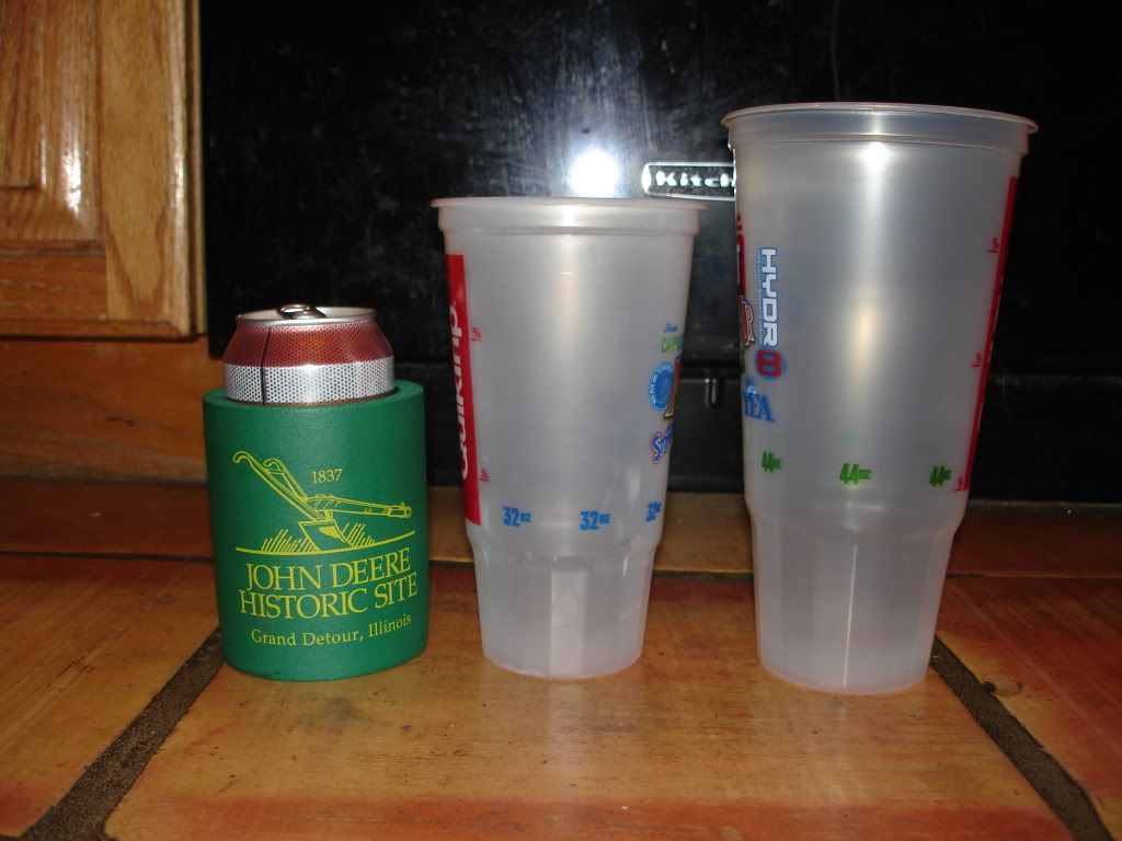 You can see that the difference in diameter is fairly substantial. I started with the can/foam sleeve. The foam sleeve measures 3.25" o.d.. The cups are obviously smaller diameter at the base but taper to a larger diameter as you go up toward the top. Ok, 3.25, 3.25, 3.25. Ah, I got it!! 3.5" o.d. exhaust pipe. Perfect fit on the can!! Ok, now to figure out how to make the cups that are going to be VERY top heavy remain seated in the pipe without assistance from the driver. With some water in the cups and some EXTREMELY scientific shaking and leaning of the pipe, I found the perfect depth that will keep both upright. I welded a piece of 1 x .187 flat stock to the inside of the pipe at the bottom to make a place for the cup/can to sit on while also providing drainage for the inevitable drip/leak etc. Now what to do with this piece of pipe. Ah, I can mount it to the side of the seat frame. Ok, it must be spaced out so much to clear the side of the seat bottom. Ok, what to use. Well, heavy wall exhaust pipe seems a bit excessive, so I should probably go with something more reasonable. 5/8" grade 8 round bar--perfect!! Nice and light, not overkill, excellent. Now to mount it. Another chunk of the .187, 1" flat stock welded to the end of the round stock, drill two holes, add a couple grade 8 bolts to the seat frame mount it about an inch above the floor and BOOM!! There it is, one perfect, lightweight (haha), cupholder. 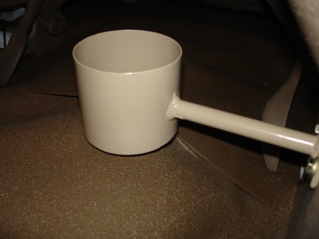
__________________
1972 K20 Suburban, 5.9L Cummins, Banks Power Pack, NV4500HD, NP205, H.A.D., D60/14FF ARB Link To Build: HERE. |
|
|
|
|
01-12-2010, 06:07 AM
|
#4 |
|
I had a V-8
Join Date: May 2003
Location: Phoenix AZ
Posts: 1,116
|
Re: The Story Of A Suburban (Lots Of Pics)
I accomplished a milestone feat this weekend. I got my D60 front axle assembly installed. It went pretty well. I did have to have my boy help maneuver the end that was on the furniture dolly. He probably weighs 50lbs soaking wet, but he did a good job doing what I told him to do and getting the heavy chunk of iron positioned where it needed to be.
As far as the 60 goes, it is really nothing too special. It was in very good shape when I got it (unbeknownst to me), but I tore it down and found all kinds of nice parts that did not need replacing. I replaced all of the seals in the diff and king pins, one lower king pin cap and the spindle seals and bushings, but other than that, all of the bearings, king pins and diff components were in good shape. I did replace all of the brake components though. I bought new GM hub/rotor assemblies, new wheel bearings and seals, new Bendix Fleet/MetLok brake pads, new GM caliper assemblies (yes brand new--ouch) and new DOT approved braided brake lines. The cool feature of this 60 is the tie rod assembly that was created for it. I am not a fan of the four foot long tie rod end that the 60's come with from GM. I like shorter ends with a long connecting tie "tube". GM never had this setup on a 60. They did it on a 10B in a 3/4T application, but never on a 1T. Well, I guess I am on my own again. I started checking diameters and found that the Dodge 1T 60's use a very short end that should be adaptable to my setup. They use a goofy 7/8-18 RH or LH thread. That left me a few options for a connecting tube. The lightest I wanted to go was 1.250" .250 wall, but then I called my steel supplier and they had 1.50" .375 wall 1026 DOM in stock. Well that made the decision real easy. I bought a chunk of it and a couple tie rod ends and headed over to Russ's 24hr Machine Shop. I brought the old tie rod as a guide for length and left the tube and ends for machining. It turned out great. The ends do not have a whole bunch of length to them, especially when you add a jam nut, but going off of the original tie rod spec, he faced the tube to a length that has only one thread showing on each side. Not so good if you have to toe it in a bunch, but I have it set a bit farther in than it was and still have the one thread. This keeps most of the threads on the tie rod end in the tube where they will do the most good. There are way more threads engaged than are required for maximum strength which is just the way I like it. New tie rod on left, original on right. New one weighs 6.3lbs more than the original: 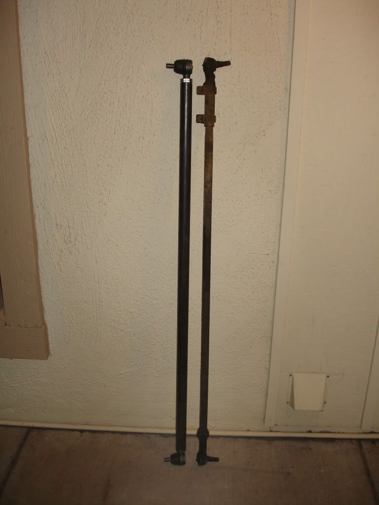 So, now that this big *****in' tie rod is made, there needs to be a way to attach a steering damper to it. I am not a fan of the u-bolt type mounting of the aftermarket stabillizer units, so Russ came up with a great idea to make a fully functional (and fully cool looking) mount. It started as a piece of 1.75" 1.20 wall tubing that I cut lengthwise with a cutoff wheel. Then I took the piece of .375 x 1 flat stock that Russ had machined a notch into and welded it above the cut. I took a piece of .250 x 1 flat stock and welded that below the cut making a big pinch clamp out of it. On the back side I used .250 x 1.250 flat stock to make two tabs to mount the steering stabilizer end in a double shear configuration. It worked out great. Minimal torque is required to keep the clamp from rotating/moving. This pic shows how the two pieces of flat stock fit together. The upper one has the milled slot in it. It is kind of hard to see, but the front of the piece has about a 1/8" lip on it that contacts the lower plate first then will pull the backside of the joint together if more torque is applied to the bolts: 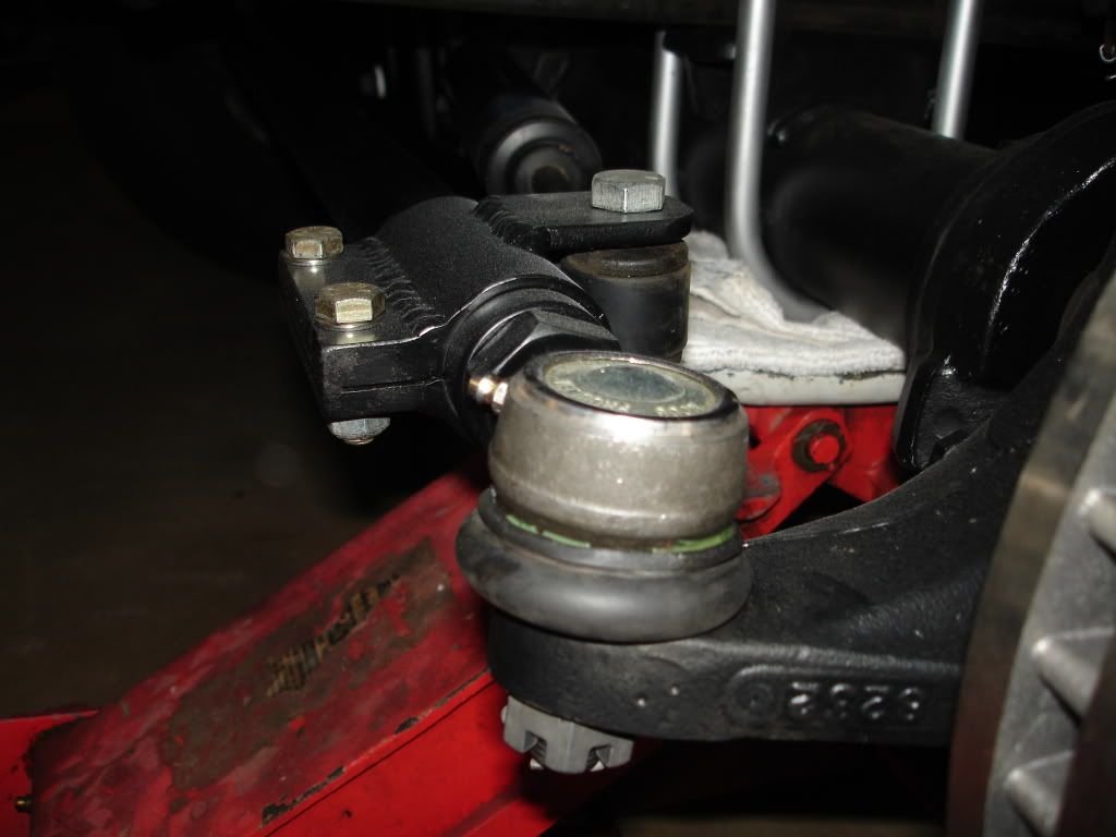 This pic shows the double shear mounting on the stabilizer end: (and the ever-present AZ dust) 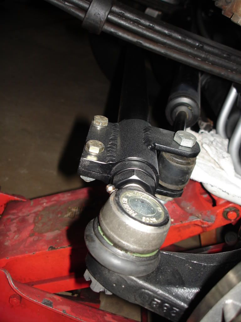 This pic shows the new hubs, rotors, calipers, and brake hoses: 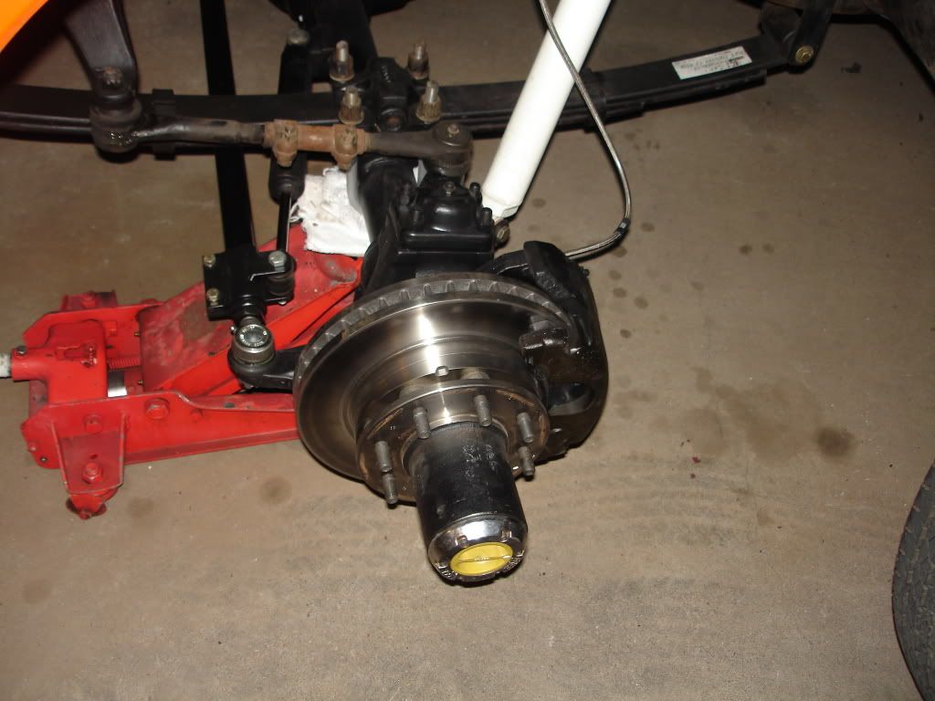 I finally have a set of Spicer hubs hanging out of my hub caps: 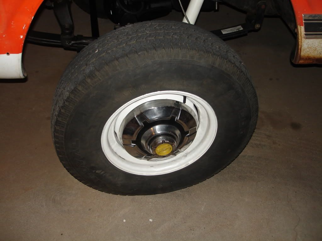 So all is good on the front end now. One problem (or benefit) with converting to a D60 front axle is that you gain one inch of height due to taller spring pad mounts and a larger tube diameter. My Sub already sits a fuzz lower than level in the back, so one inch is an issue for me. I picked up a set of Zero Rates awhile back and figured this would be the perfect application of them. I have a probelm though. I have a vibration at 60-65 that is pretty noticable and it continues through 82 when the motor lays down. I measured the angles of the transfer case and rear diff and came up with the pinion needing to come down 2.3 degrees to match the transfer case. I took the Zero Rates over to Russ and he cut them at 2.5 degrees to try to keep the pinion at a zero more often than it would at 2.3 degrees. I threw them in the back and went for a drive. Well, the vibration between 60-65 went from bad to worse--wow. But, the vibration at 65 and above is barely noticable if it exists at all. Sweet. I think the easy fix for this problem is not to drive between 60 and 65. For the time being, that is what I am going to do. So, all in all, I could not have been more pleased with the whole ordeal. There were a few small issues here and there, but nothing that was too difficult to deal with.
__________________
1972 K20 Suburban, 5.9L Cummins, Banks Power Pack, NV4500HD, NP205, H.A.D., D60/14FF ARB Link To Build: HERE. |
|
|
|
|
01-12-2010, 01:50 PM
|
#5 |
|
Registered User
Join Date: Feb 2008
Location: Albuquerque
Posts: 359
|
Re: The Story Of A Suburban (Lots Of Pics)
Thanks.
Now you got me thinkin about changing my 60 tie rod... Add one more project to the list. Mick |
|
|
|
|
| Bookmarks |
|
|


 Hybrid Mode
