
|
|
|
 01-29-2021, 08:41 PM
|
#1 |
|
Registered User
Join Date: Sep 2019
Location: Maynooth, Ontario, Canada
Posts: 174
|
Re: Project Fargolet
your doing a super fine job, keep at it
__________________
http://67-72chevytrucks.com/vboard/s...82#post8619382 |

|

|
|
02-01-2021, 10:41 AM
|
#2 |
|
Registered User
Join Date: Sep 2018
Location: Ontario
Posts: 799
|
Re: Project Fargolet
that wiring looks very neat and clean, nice work. (so does everything else)
keep at it, and thanks for the updates.
__________________
https://67-72chevytrucks.com/vboard/...=797726&page=3http://https://67-72chevytrucks.com/...=797726&page=3 51 Chev 5 window on S10 with SBC 1958 Pontiac Wagon build https://67-72chevytrucks.com/vboard/...d.php?t=849781 |
|
|
|
|
02-26-2021, 07:37 PM
|
#3 |
|
Registered User
Join Date: May 2009
Location: Grey County Ontario
Posts: 207
|
Re: Project Fargolet
Thanks guys. I have been trying to pick up the pace a bit, but everytime I do something I spot 2 more things Id forgotten about! Continuing on with my to-do list I tackled the front bumper. My options here were a bit limited due to the grill design of the Fargo. The grill openings limited me to using the inner sides of the S10 frame rails (which had to be shortened a fair bit to sit behind the curved grill). To deal with this I capped off the ends of the rails with some plate steel, and then built brackets to reach the bumper. These trucks didnt have bumper brackets- the bumpers bolted right onto the front frame rails. I wanted adjustability, so I made 3 inch mounts that sit inside the bumper (which is 4 inches inside). By mounting the bumper at the mid point, I have a half inch adjustability up and down at each mount (I made a bunch of big shim plates to allow me to fool around with levelling things out-I still need to drill the holes in them). Oblonging mounting holes on the mounting brackets if/as required will allow for minor side to side and in/out adjustment. Heres what I ended up with:
  The issue of the gas filler tube was something I had been grappling with for a while. I really like the stock look of the Fargo with the filler cap in the corner of the cab, just behind the drivers door, and I wanted to keep that original look. In the end, I opted to put the filler in the box, and leave the stock filler mounted in the side of the cab (modified to protect against anyone ever accidentally trying to fill my cab up with gasoline!). I then got working on the new filler. I decided to come up through the bed, and conceal the filler inside a permanently mounted toolbox. I wanted the new filler to come straight up from the S10 tank and out of the bed at a 90 degree angle. The S10 tube is bent, and after a few measurements I had angle figured out. I ordered a Gates model #24712 45 degree filler hose tube and this gave me a perfect angle. The vent tube also needed to be cut and welded to a new angle, but this was just a quick cut and some mig welding. One thing I noted was that the check ball was missing from my S10 fuel filler. The plastic tabs that prevent it from falling downwards were still in place, so how on earth could this thing be missing? Once again, thank god for that old Blazer in my driveway. After a miserable half hour in rather frigid temps I had removed the Blazer filler and confirmed that the check ball was still in it. Heres a shot of the S10 filler, the Blazer filler and the check ball that came out of the Blazer filler:  Heres the S10 filler, with the excess length removed to shorten it up: [url=https://flic.kr/p/2kE66GA]  By gentle bending of the plastic tabs, you can remove or insert a fresh check ball. A few hours later I had my modified S10 filler done and coated with some paint (and I can now say that I have performed my first ball transplant  ) The modified filler is about 5 inches shorter than stock. Here is the finished filler: ) The modified filler is about 5 inches shorter than stock. Here is the finished filler: Next was the bed. I spent a ton of time getting the correct heights for the bedsides and lining everything up nicely. Actually, nicely may be an overstatement. This truck was bashed so badly that its simply not possible to line things up perfectly, so I focussed on eliminating things that catch the eye and basically averaged out all the errors. For the bed itself I opted for 14 gauge checkerplate steel. It will quickly rust to blend in with the rest and it keeps me from losing more bed depth. If I ever decide that I want the look of old wood, I can easily get my hands on old barn boards around here, and mount them on the bed. I could even use relatively thin boards as they would just be a veneer over the steel. With the help of an able bodied assistant I was able to cut that sheet of checkerplate to length, trim out the spot for the filler tube, and slide the whole mess into place, sort of ..On our first try it got stuck between the bedsides and we couldnt figure out why. It turns out that the 48 inch width of the sheet was actually 48 ¼. After a long slice with the angle grinder it slid right in. Angle strips for the bedsides are not something that I can easily pick up around here, so I just used the thinnest angle iron I could find (still a bit thick for my liking, but plenty strong!). Instead of welding the strips to the bedsides I opted to use bolts as I dont know what the future holds for this truck and I want to be able to make changes easily. The bed rests on a sturdy frame that I made for it. The frame is 100% square and sets the box right into place without the need to measure anything. The supports on the frame will also keep the checkerplate from sagging if I walk in the bed. Realistically the heaviest load this thing will ever see is a person walking on the bed. Now it was just a matter of drilling a bunch of holes and tossing in nuts & bolts.  Hindsight thought: If I ever do this again, I will just reuse the S10 bed and crossmembers. The tiny bit of extra bed depth that I got was not worth the hassle and cost of making the fancy frame. With the bed on it was time to finally finish off the fuel filler. As Id said earlier, I really wanted to keep the outsides of this thing looking as original as possible, including keeping that cool old filler tube that sticks out of the cab behind the drivers door. I however had no intention of running fuel through the cab, so heres what I did to keep the look. The original filler tube was left in place, but it was cut off inside the cab and a plate was welded inside:    And now I had that original look, without the possibility of anyone ever sticking a gas nozzle into it and filling up my cab:  Of course I will need to add gas to this thing so I added the modern S10 filler tube but kept it out of sight. My filler tube now comes up out of the bed ...  ...and it lurks inside of an old ammo box . 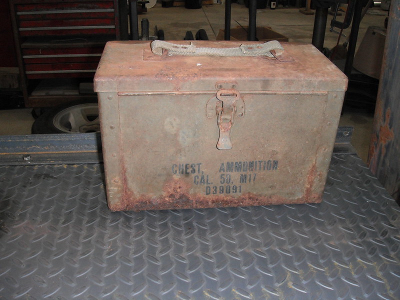  I will eventually replace the old ammo box with a larger toolbox that can also hold a jack, flashlight, emergency repair tools, etc. but right now with the covid lockdown in effect I have no swap meets or flea markets to go to in order to hunt down neat old stuff. And heres the tail end of things now:  Thats enough for this post. More to follow! |
|
|
|
|
02-27-2021, 09:41 PM
|
#4 |
|
Registered User
Join Date: Sep 2019
Location: Maynooth, Ontario, Canada
Posts: 174
|
Re: Project Fargolet
I like it....I would keep the ammo box ...It's got a good look and feel to it.....
__________________
http://67-72chevytrucks.com/vboard/s...82#post8619382 |
|
|
|
|
02-27-2021, 10:03 PM
|
#5 |
|
Registered User
Join Date: Nov 2014
Location: somewhere, PA
Posts: 1,053
|
Re: Project Fargolet
dude, i might steel the ammo box idea! i have an old school job-box tool lock box i think I'm going to use for enclosed storage in the bed, and would have just enough room left for something like that next to it.
|
|
|
|
|
02-28-2021, 01:55 PM
|
#6 |
|
Registered User
Join Date: Aug 2019
Location: Würzburg Germany
Posts: 46
|
Re: Project Fargolet
A lot of grate work on that truck. Grate idea to solve different problems. Keep on that grate work.
So long Arnd |
|
|
|
|
03-01-2021, 10:25 AM
|
#7 |
|
Registered User
Join Date: Sep 2018
Location: Ontario
Posts: 799
|
Re: Project Fargolet
Good to see more progress.
Looks Great
__________________
https://67-72chevytrucks.com/vboard/...=797726&page=3http://https://67-72chevytrucks.com/...=797726&page=3 51 Chev 5 window on S10 with SBC 1958 Pontiac Wagon build https://67-72chevytrucks.com/vboard/...d.php?t=849781 |
|
|
|
|
03-04-2021, 02:46 AM
|
#8 |
|
Senior Member
 Join Date: May 2007
Location: Doodah Kansas
Posts: 7,761
|
Re: Project Fargolet
nice problem solving!
I think the check ball is an anti-siphon device.
__________________
the mass of men live lives of quiet desperation if there is a problem, I can have it. new project WAYNE http://67-72chevytrucks.com/vboard/s...d.php?t=844393 |
|
|
|
|
03-12-2021, 06:33 PM
|
#9 |
|
Registered User
Join Date: May 2009
Location: Grey County Ontario
Posts: 207
|
Re: Project Fargolet
Thanks guys, and youve talked me into it. The ammo box stays! I will look at a secure way to store the jack and a few tools in the cab.
And thanks Rusti. I see you are from Wurzburg. My mom is from Arzberg, just down the road from you. Getting parts there must be a lot of fun. Joedoh: If Id have known that I would have just ignored it! I had worked on the front bumper a short while ago, and just needed to drill holes in the shims to finish that job. I did that and then played around with them to get the best fit. I also remembered that I had a bracket that came with the truck, mounted on top of the front bumper. I dug it out and reinstalled it. I have no idea what its purpose was, but it's a million years old and came with the truck so Im keeping it attached. A side benefit is that it helps hide the fact that I had to use shims to average out the errors on the front end of this thing. Heres a couple of shots of the bumper and that bracket. If anyone knows the purpose of it, feel free to tell me: 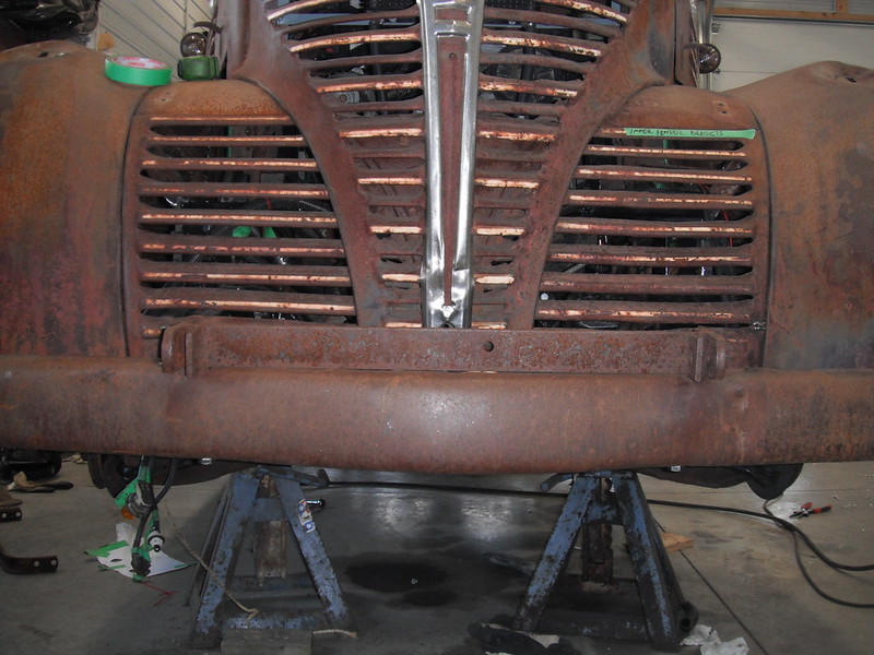  I received a parts order from Rockauto and got to work under the hood. First was the lower rad hose. I have been using The Formula from Skymangs S10 Swap Thread, and I have the Speedway universal 19x22 rad with the outlet cut and rewelded so that it points outwards rather than inwards. As a result, I now needed a custom hose as the distances and angles were all wrong, plus the Speedway rad outlet is 1 ¾ inch rather than the 1 ½ inch that stock S10s have. I went through the various manufacturers hose charts and lost my mind trying to find something to fit. I eventually came up with a painfully easy solution. First, I bought 2 stock S10 lower rad hoses (1 ½ inch hose with one end flared for 1 ¾). I put one hose on the engine side, just like it's supposed to go, then I grabbed the 2nd hose and spun it 180 degrees so that it attaches to the 1 ¾ inch radiator outlet. Here are the 2 hoses, which actually have a straight stretch where they want to line up with each other:  Now it was just a matter of picking a spot along that straight stretch and cutting both hoses. With the addition of a 1 ½ inch hose coupler I ended up with this. Length and angles are just right:  Once installed, this is what I had. Fits like a glove:  The upper rad hose looked like it was going to be fun, as its 33 inches long and shaped like a snake. I fooled around with it for a bit, then discovered that if you loosen the clamp on the thermostat end and twist the hose clockwise, it ends up looking like this:  Now I just had to add a piece of hose with a 90 degree bend that fit the Speedway rad (1 ½ inch). A 1 ½ to 1 ⅜ coupler then joined the 2 hoses.  Im not sure that Im fully happy with it, but it will work for now. Before I get rid of my parts truck, I will scavenge the thermostat housing and perhaps fool around with fabbing a new outlet that goes straight up. This would shorten the length of the upper rad hose, and would look a lot neater. But thats a chore for next winter. The heater hoses were wonderfully simple. One of them just needed to be shortened by an inch or so and it fit the Mopar heater perfectly. The other S10 heater hose is a larger diameter (why would you use 2 different diameters to plumb the heater?), but I was able to easily connect it by simply adding an adaptor that throttled it down to 5/8ths and then plugging the 5/8ths section into the heater. Again it fit like a glove (dumb luck). The next item out of the Rockauto box was a wiper arm and blade. I had found plenty of wiper arms and blades on the specialty vendor sites, but then I checked the Rockauto site out of idle curiosity. Sure enough they list a wiper arm and blade for my truck. The arm is an Anco 41-01 and it is supposed to fit most vehicles in the 30s to 50s timeframe. The arm comes with adapters to fit common wiper posts (or whatever you call the spots where the arms go on). My kit had an adapter, but it was too tight to fit by about 10 thousands of an inch. My wiper posts were exactly 0.25 inch, and I didnt want to risk overdoing it by just running a ¼ inch drill bit through the adapter. To remove the small amount needed I simply rolled up some 220 grit sandpaper into a tube shape, stuck it into my drill and ran it through the adapter. It only took a minute or two, and I was able to sand away just enough that I had a nice tight fit. Here is the Custom Inner Bore Enlargement Tool (patent pending):  And here is the adapter, pressed onto the wiper post and secured with 2 tiny set screws:  The arm could now be pressed onto the wiper assembly, and it was time to tackle the next problem. Vacuum motors have a kind of silly charm to them, and I have a pair that work, however I am fully aware of their limitations. One thing I had read about before ordering the Anco conversion arms was the fact that the spring in these arms is hellishly strong. This makes for great wiper to glass contact, but it easily overpowers the ability of vacuum wipers to actually be able to move the blades back and forth. I tested my wiper arm and I realized right away that it was way too strong for my vacuum wipers. I read a few posts where people looked for softer springs or tried different techniques to change the strength of the springs, and as I was fooling around with the unit I had a flashback to physics class and I remembered Hookes Law which states more stretch equals more force (or something like that). Deductive reasoning led me to the idea that less stretch equals less force, so I grabbed a piece of galvanized page fence wire (strong stuff) and I made a little link that would result in less stretch of the spring. Heres a shot of the Anco arm as it came:  And heres a shot with the little link installed. The difference in down-pressure of the arm is night and day, and if I need more or less force I just have to bend up a new link that's either a tad longer or shorter. It takes only seconds to do and hopefully will allow me to individually adjust each side to the strength of each sides vacuum wiper.  I wont be able to do anything further until I have the windshield glass installed and the engine running to provide vacuum, but for now it is looking promising. I had the assistance of my son Brian (we have done a couple of builds together), so I enlisted him to help me disassemble the doors. The doors were in wonderful condition (straight and no rot whatsoever), however they did have some issues. First, I would like to show you my favourite farmer-fix of all time:  Yup, you are seeing that correctly. At some point the door latch mechanism failed, so a household door knob and latch was installed. If I didnt have to go through a safety check I would be inclined to leave it alone, as I think it's the most charming feature of the truck! Unfortunately I do have to replace it, and thats gonna be fun. Those door latch mechanisms are only sold in pairs, they are horribly expensive, and they are currently out of stock at every vendor on earth (I checked). I may go for a set of bear claw latches which are safer and far cheaper (and are actually available). In the meantime I have tons of stuff to do. The windows in the doors had been cranked down to the fully open position, and the regulators were stuck. We managed to get the doors fully disassembled and found some pleasant surprises. First was the glass: I had budgeted for new glass as my windshield glass was yellow and delaminated. The door glass however appears to have been replaced at some point as it was in mint condition in both doors, not even scratched. The next pleasant surprise was the regulators. A quick check showed that nothing was broken and all the gears were in alignment. The regulators had simply sat too long, and rust had built up and old grease had hardened. A thorough cleaning with hot soapy water, some wire brushing, a few spritzes of brake cleaner into some hidden crevices and some gentle back and forth turning of the cranks got things moving nicely. Once the gears were given a coat of lithium grease and the bushings were oiled, both regulators could be turned effortlessly. Before and after:   The doors were then set aside and I got to work on a tail light bracket. The Fargo came with a single taillight and licence plate bracket, so a 2nd one was needed for the passenger side. They certainly werent stingy with metal back in the 40s, as the original bracket was massive. Recreating the exact shape would be a pain as it tapers down from a thick base, however the licence plate covers most of it from view so I was able to cheat a bit. Heres the original driver side bracket for light & licence plate:  I found some heavy rod and fabbed a new bracket using the old slice & dice method. This rod was heavy enough that I was able to get reasonably close to the size of the original bracket. After bending it to shape and welding up the slices I had a reasonable facsimile of the real thing.   I then added the plate that mounts the light (no idea what the original is like so I just eyeballed the driver side and used that as a guide). I bolted the light plate to the bracket and then got fancy with my welder and grinder, turning the little nuts and bolts into fake rivets to mimic the driver side. It was of course bright and shiny (we cant have that!) so I stuck it in a plastic sandwich bag, immersed in vinegar, hydrogen peroxide and salt. Heres the old and the new:  And here they sit with the bright and shiny new taillights that just got delivered:  More to follow! |
|
|
|
|
03-12-2021, 09:16 PM
|
#10 |
|
Registered User
Join Date: Jan 2014
Location: edgeley sask
Posts: 89
|
Re: Project Fargolet
Pretty sure that bracket was likely for a tow bar....
|
|
|
|
|
03-12-2021, 09:36 PM
|
#11 |
|
Registered User
Join Date: Nov 2014
Location: somewhere, PA
Posts: 1,053
|
Re: Project Fargolet
radiator hoses drive me nutz, i like the execution.
|
|
|
|
|
03-13-2021, 12:41 AM
|
#12 |
|
Senior Member
 Join Date: Aug 2010
Location: Shasta Lake, CA.
Posts: 1,619
|
Re: Project Fargolet
Yep that bracket is for a tow bar . Probably got the truck home at some point in its life .
BTW there is a gas cap for the S10 that allows you to fill without having to remove the cap . It has a spring loaded trap door the you put the nozzle through , it even works with the vapor recovery nozzles. Do a search for 96 S 10 push through gas cap , I found a Tanks Inc cap at Summit Racing for $ 21.95 I put one on my Caprice it made filling a breeze with the license plate tipped part way open , no more screwing around in the tight space .
__________________
Glen & Jane's Rides 57 GMC NAPCO Long Bed V8 4 speed Bought 2008 7 other cars & trucks , 5 trailers '56 Chevy Long Bed I6, 4 speed Bought 1990 Sold 8.22.2020 56 GMC Suburban Pickup V8, 4 speed Hydramatic Bought 1996 Sold 10.11.2020 My Other Tinkerings http://67-72chevytrucks.com/vboard/s...75#post8967275 Last edited by G&R's57GMC; 03-13-2021 at 12:59 AM. |
|
|
|
|
03-15-2021, 10:11 AM
|
#13 |
|
Registered User
Join Date: Sep 2018
Location: Ontario
Posts: 799
|
Re: Project Fargolet
Great work.
Fabbing that passenger side light bracket was great, just think how many people will see that and have no idea what was involved to do that. As always, great work with great pics and explanations, Thanks for sharing.
__________________
https://67-72chevytrucks.com/vboard/...=797726&page=3http://https://67-72chevytrucks.com/...=797726&page=3 51 Chev 5 window on S10 with SBC 1958 Pontiac Wagon build https://67-72chevytrucks.com/vboard/...d.php?t=849781 |
|
|
|
|
03-26-2021, 06:29 PM
|
#14 |
|
Registered User
Join Date: May 2009
Location: Grey County Ontario
Posts: 207
|
Re: Project Fargolet
Thanks guys, and G&Rs57GMC: Thanks for the tip about those caps, but I am OK here. The photo makes the filler tube look kinda hidden, but in fact I have all the room in the world to take the cap off and place a fuel nozzle in.
The air filter was giving me fits due to the tapered front end of the truck. Space was at a serious premium, and it took a while before I found something that would fit. Thankfully both K&N and Spectre have very good dimensional lookups on their sites which made things a lot easier. I was still having trouble getting the best fit due to the weird size of the S10 MAF inlet (3 ¼ inch), but I found a posting that said to just get a 3 inch filter and hit it with a die grinder (thanks Joedoh!). I found a stubby cone filter (Spectre Model 8168) that fit nicely into the corner where the hood, inner fenders and rad meet. I also noted that these filters are called racing filters. As a youth I constantly read magazines like Hotrod and Carcraft, so I just know that filter is good for an extra 25 horsepower at the rear wheels (geez the crap I used to believe!!!!!!). Anyhow, that filter is interesting as it also has an interior cone to provide additional filter surface area (likely to make up for its small overall size):  It also fits 3, 3 ½ and 4 inch inlets by the use of adaptor rings that are included with the filter.  The adaptor rings are rubber, and I discovered that the 3 inch ring can easily be stretched over the 3 ¼ MAF. Then the 3 ½ inch ring can be easily stretched over the 3 inch one. Then the 4 inch ring can easily be stretched over the 3 ½ inch ring. In the end, it all fit without any grinding or fiddling around, just by doing the rings one at a time. While the new filter assembly did fit, it could not simply be clamped on as it would be rubbing against the inner fender and banging around as I drove, and it also sat exactly where the power steering filler tube was. Some kind of bracket was going to be needed. The power steering filler tube enters the pump through a grommet, and the top of the tube is held in place by a bracket. This is convenient as you can re-orient the tube by simply unbolting the top bracket, spinning the tube to wherever is convenient, and then fabbing a new bracket.  The air filter and power steering filler tube could share a bracket and I got lucky here. My S10 came with the A/C deleted, so there was a rather convenient mounting pad where the old compressor used to sit. A few hours later I had this:    Everything is firmly held in place with decent clearances to prevent rubbing. When I had earlier removed the old windshield glass I noticed some rust in the frame. Im not quite sure how they manufactured this frame, but here is the joint where the upper and lower halves meet:  When I saw the rust inside that weird shape I dreaded tackling that job. However in the end (as usual) I imagined it to be a far nastier job than it actually was. Heres the lower section of the windshield sitting on my welding table:  My initial concerns with rust centered around the fact that the rust was in a deep channel (the channel where the glass sits), so access would be difficult. I eventually found a way to deal with it. Heres a shot of the rusty base of the channel, with the lower corner actually rotted through for a distance:  Welding access wasnt the greatest because the mig nozzle was far too big to fit into the channel:  By playing with the settings, I was able to compensate for the lengthy stick-out of the wire. The metal I was welding to was very thin due to the ravages of the rust, so it was a matter of starting at a thick area, welding a small spot, waiting a couple of seconds for the weld to solidify and cool, then welding another spot that just touched the previous weld spot, then waiting again .it was slow work, but by always touching the previous weld spot I had an area that could take the heat without blowing through.  For grinding down the welds I just used an air cutoff wheel, gently going back and forth in the channel. It fit right down there and worked like a charm (but did require a lot of patience as it was a very slow process):   No, it aint the prettiest work, but there is no longer a rusted split in the metal, and given the limited access I was quite happy with it! This corner was the worst spot, as it was missing a lot of metal due to rust:  Again it was just a matter of doing the zap & wait routine, followed by gentle smoothing with the cutoff wheel:  I spent a good 3 hours fixing that lower channel, but it was well worth the time. While in the midst of all these little jobs, I took the time to deliver my driveshaft to a place that does truck repairs to have it shortened. I was a little apprehensive as the driveshaft from my S10 is encased in a weird black tube of some unknown (but very strong) material. The guys at the shop figure its some kind of deadener for sound or vibration, and it turns out that underneath it all its just an aluminum tube. They shortened it up by 10 inches and balanced it for me as well.  When I went to install the shaft, I found that a little work was needed to get the angles right. Axle shims come in ½ degree increments, and my closest fit was a set of 3 degree shims. When I installed my transmission cross member earlier in the build, I purposely welded it in a tad low (its way easier to add a shim than it is to lower a cross member). Being able to play with shims at the transmission mount makes it a snap to match angles. By making a spacer out of 7/16ths aluminum, I was able to get a perfect match of angles (5.3 down at trans, 5.3 up at axle). The driveshaft has a down angle of 6.9 degrees, giving me 1.6 degrees relative to each end, which is smack dab in the middle of the recommended 1 to 3 degree range. Thats it for now. More to follow! |
|
|
|
|
03-26-2021, 09:02 PM
|
#15 |
|
Registered User
Join Date: Jan 2014
Location: edgeley sask
Posts: 89
|
Re: Project Fargolet
Excellent work and excellent explanation of your techniques and processes. This is the kind of effort that really helps others with their projects. It is so satisfying when one does tackle a problem and get through it with such good results. These vehicles are such a fun challenge. You're progressing nicely.
|
|
|
|
|
03-26-2021, 09:28 PM
|
#16 |
|
Registered User
Join Date: Sep 2019
Location: Maynooth, Ontario, Canada
Posts: 174
|
Re: Project Fargolet
What edgeley said ��
__________________
http://67-72chevytrucks.com/vboard/s...82#post8619382 |
|
|
|
|
03-27-2021, 09:07 AM
|
#17 |
|
Senior Member
Join Date: Sep 2017
Location: Bryan, Texas
Posts: 2,292
|
Re: Project Fargolet
Thanks for sharing.
__________________
8man-aka Robert 1948 on a S10 Frame, small block with a carb 1954 Cab, 53 Front and Bed, 50 Doors, S10 Frame, Power TBD Build thread: "]http://67-72chevytrucks.com/vboard/showthread.php?t=746899&highlight=wife%27s+48[/URL] [/URL]http://67-72chevytrucks.com/vboard/showthread.php?t=840204 |
|
|
|
|
03-29-2021, 10:26 AM
|
#18 |
|
Registered User
Join Date: Sep 2018
Location: Ontario
Posts: 799
|
Re: Project Fargolet
good work, as always
keep it going, and thanks for sharing
__________________
https://67-72chevytrucks.com/vboard/...=797726&page=3http://https://67-72chevytrucks.com/...=797726&page=3 51 Chev 5 window on S10 with SBC 1958 Pontiac Wagon build https://67-72chevytrucks.com/vboard/...d.php?t=849781 |
|
|
|
|
04-03-2021, 12:24 AM
|
#19 |
|
Post Whore
Join Date: Aug 2014
Location: Sacramento, CA
Posts: 10,818
|
Re: Project Fargolet
great work
|
|
|
|
|
04-06-2021, 08:21 PM
|
#20 |
|
Senior Member
Join Date: May 2007
Location: Doodah Kansas
Posts: 7,761
|
Re: Project Fargolet
oh man the windshield.. I did two 41 chevys and the first one, I bought a whole new windshield frame and all, it was like 800 bucks. on the second, I said the og frame wasnt too bad, and spent $500 on new connectors, new center strip, new glass, and THEN spent a week or so welding up the channel. ugh. wasted a week to save $300 and probably didnt save anything. you did a nicer job than I did for sure!
the wrap on your driveshaft is carbon fiber! and they do that because the s10s are so low they can risk dinks on the driveshaft when you run over stuff, which is reeeeallly bad for aluminum and balance both. crazy good work! keep it up!
__________________
the mass of men live lives of quiet desperation if there is a problem, I can have it. new project WAYNE http://67-72chevytrucks.com/vboard/s...d.php?t=844393 |
|
|
|
|
04-14-2021, 07:43 PM
|
#21 |
|
Registered User
Join Date: May 2009
Location: Grey County Ontario
Posts: 207
|
Re: Project Fargolet
Thanks guys! I spent a lot of time on this site before starting to work on the Fargolet, just reading other peoples build threads to get ideas about how to do stuff, and it saved me a ton of time and aggravation. Forums like these are the greatest way to swap info and ideas.
Joedoh, those windshields really are a PITA to work on. I lucked out as mine was salvageable and I ended up with less than 200 bucks in it for glass, seal, setting tape and sealant. The alternative was a new one which would be pushing 2 grand by time I got it in my hands here in Canada. And Tempest67, you were right, that stuff around the driveshaft is carbon fiber! Made some more progress in the last couple of weeks. We installed the windshield glass which went quite well. We then got the seal pressed into the groove around the frame (very slow work with a screwdriver to press it into place), and then we mounted it. The seal is new and stiff, and the fact that my shed is kept at 55 degrees doesnt help soften that rubber. Pet Peeve: There are 6 different ways that the windshield seal can be attached to the frame, 5 of which are wrong. Would it kill the suppliers to include a sketch? Heres the results:   The doors are on in the above picture, as I did some work on the hinges. A couple of the hinges were badly worn, allowing some sag. I will likely need to do a bearclaw latch install soon, so that sag had to be taken care of first. The worst offender was the driver door bottom hinge, which had worked its way into a nice egg shape:  I have a drawer with assorted sleeves in it (no idea where I got them!), and I was lucky enough to find one that fit like a glove (after a little grinding that is).  Good as new!  And now, fun with gauges! I had been putting off dealing with gauges for a while, and finally decided to get at it. While I have been trying to use everything from the S10 donour, I ran into a snag here. The speedometer looked doable, but the odometer is part of the tach assembly. My dash has one large round hole for a speedo and no spot for a tach (and I dont particularly want a tach anyhow). I need an odometer though, so I opted to order a new speedo/odometer. After a bunch of research I decided to use a gps style as this bypasses issues with matching electronic signals. The one I ordered also happened to have built in lights for turn signals and high beams, thus saving me from more fabbing. Here it is, along with a filler ring (new speedo is smaller than the old, so a filler was needed). I will use the filler as a spot to mount a few warning lights later on.  To get a good signal, the gps receiver needs to see the satellites above, but the Fargo has a vertical windshield and I suspected reception may me spotty at best. I did however have a rather convenient outside location with a wonderful view straight up (my ammo box fuel filler), and the gps cable was long enough to reach.  The other 4 gauges took a little more thinking. In keeping with the theme of the build, I wanted to reuse the S10 gauges as they worked fine and were compatible with all the senders (and of course they were free!). This turned out to be a fiddly job, but interesting and actually fun. Heres what I did, (and keep in mind that this is a 96 donour, so I cant say if it works for the square bodies or the 98 and onwards types). First came the S10 instrument panel disassembly. This is just a matter of removing the torx screws on one side, and then separating the 2 halves of the panel by pushing down on all of the gauge studs bit by bit until the 2 halves come apart:   Removal of the gauges involves 2 steps. First the needle has to be removed. Here is a shot of the needle being pulled off of its mount by a special tool. If anyone wants one of these tools, send $30 and a stamped, self addressed envelope to me and I will provide one. 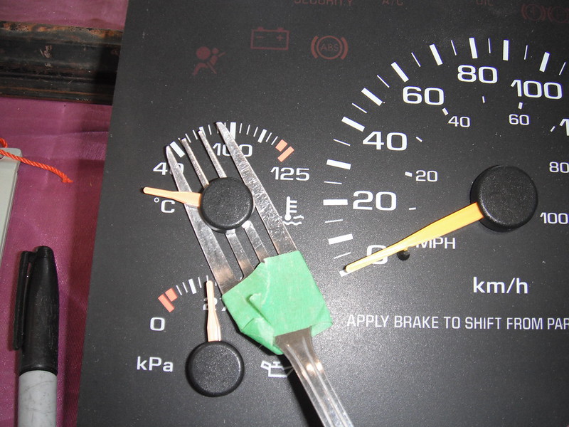 Once the needle is off, the gauge can be unscrewed by a #8 Torx driver (or some really tiny socket). The screws are some kind of self tapping jobs that hold the gauge into the plastic panel, and they are very slim. Heres an S10 gauge. Its small, and its deeper than the original gauges in the Fargo:  Next I had to figure out how to mount the S10 gauges using the Fargo housings. The old gauge faces were incompatible with the new gauges. The Fargo gauges are mounted upside down (the needles point downwards) and the needles rotate counter clockwise. S10 gauges (and pretty much all others) point up and rotate clockwise. Here is an original gauge panel:  And here is how the original gauges and panels went together:  I got a piece of plastic (no idea if it's plexiglass or lexan) and cut it to fit the shape of the back of the gauge housings. After a ton of very careful measurements I was able to drill out holes for the gauge needle shaft and for the self tapping screws (they need starter holes or you will snap them). The drill bit for the self tapping screws was so small that it would not hold in any chucks I had, so I ended up putting the bit in a dremel with an extra small collar. The gauges could now be affixed to the rear of the housings. Heres one of them temporarily screwed in place:  For the gauge faces I could have cut up the S10 panel and tried to use those, but I wanted something that looked a little more period-correct. I took a bunch of measurements and then enlisted my wife to help me out with decals. She is a whiz on the computer and after a couple of hours we had our new faces. We printed them out on paper to let me test the fit, and once I was happy with it we reprinted them on clear, self adhesive label sheets (Avery brand). They worked OK, but they dont print a deep enough black colour. Perhaps Ill try a different brand in the future.The inside of the housing had to be painted, and the original 6 volt bulb replaced with a 12 volt one: 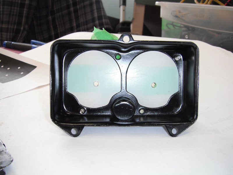 Here is one of the clusters with the lower face sheet in place. The 3 dots align exactly with the S10 gauge high, low and mid points and they sit directly under the needle:  Here is that housing with just the voltmeter installed. To get the needle in the correct spot we grabbed a car battery and tested its voltage, then hooked up the gauge and set the needle to correspond to the reading we got on the battery. Attaching these needles is simply a matter of pressing them onto the shaft (no tools required).  Another decal then gets placed on a thin sheet of plastic that covers the housing, and this sheet labels the gauge. The Fargo housing cover holds this sheet of plastic in place.  When it's all put together it looks like this (only one gauge installed right now as I had not yet gotten to debugging everything).  Next came figuring out how to attach wires to the studs that power the S10 gauges. I was having a tough time finding the special clips that will attach to studs until I posted a query on the 47-59 Board. Another member found them for me (thanks 1project2many !) but they appear either unavailable or out of stock right now and I needed them right away so I had to improvise. I can always switch to the good clips later as I always leave sufficient wire to fix screwups down the line. Heres what we did for now (my son Brian was providing his engineering expertise and its a good thing. He can instantly make out whats happening in a wiring diagram, and he is crazy good at micro soldering). Brian brought up a bunch of these tiny round connectors (neither of us know what they are called), and it turns out that they fit nice and snug on the S10 gauge posts:   From this point it was just a matter of wiring up the 2 gauge pods containing the oil/temp/volts/fuel gauges, as well as the new speedo and then adding loom. Each gauge pod has its own connector so that removal is easy.  Next came the Prindle (the PRNDL indicator). It's always nice to be able to tell what gear you have selected, so this unit had to come out of the S10 cluster and into the Fargo. The prindle is run by a big circuit board within the S10 instrument panel, and the best option seemed to be taking the entire thing out and mounting it in a flat spot behind the dash. Heres how we did it. This plug provides the electrical inputs that the pringle needs:  The plug was depinned:  And the plug was attached to quick connects that led to the S10 harness:  The prindle assembly sits in a plastic box that Brian created on a 3D printer. 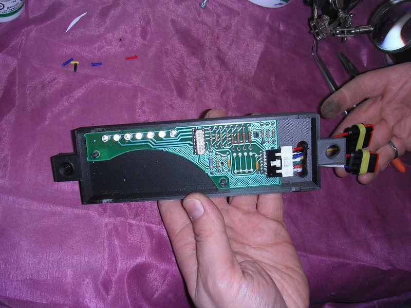 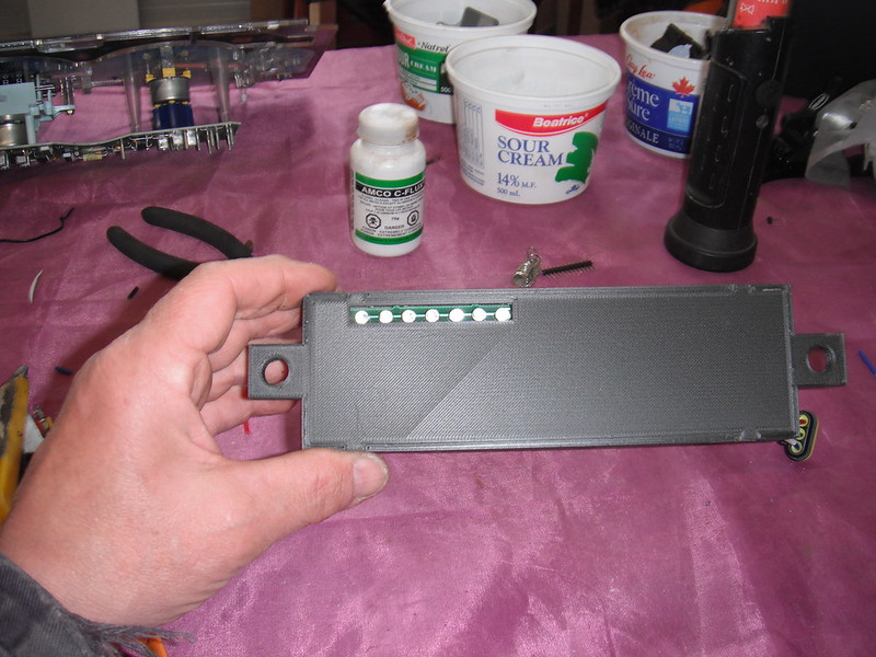 There was a convenient big, empty flat spot on my dash that would easily accommodate the prindle assembly. To mount it I welded 2 studs into the inner face of the dash so that installation or removal just involved loosening 2 nuts and unhooking the quick connector. To be able to see the lighted display I would have to cut a narrow slot into the dash. I was initially reluctant to do this (I hate cutting original antique metal), but then realized how silly this was. Right above the spot where the prindle display slot would sit is a giant hole cut into the dash by some previous owner, and from the quality of the cut I suspect he did his bodywork with a chainsaw. I stopped overthinking things and just got to work cutting the slot into the dash. The hole still needs to be cleaned up, and I have to create some sort of cover that labels the leds that indicate the gear its in.  Heres where it all sits now:  The ring around the speedo has 3 holes for small LED warning bulbs. I had picked up some bulbs but after setting them in place and seeing how they looked I ripped them out (they looked like they belonged in a Honda Civic with a whale tail spoiler and a 4 inch exhaust pipe!). I will find something a little more subtle. After looking at my work, I got to thinking about Gauges model 2.0. I think I will play around with a different design that mounts the gauges deeper into the housings. It will be a little trickier as this obscures the internal light somewhat, but I think I will get a better look that way. I also have to find transparent sheets that can accept black ink better when I print them. For now though I know that I can reuse the S10 gauges, and pulling these out to make them better will be a fun winter project next year. For now I really just wanna go drive this thing. More to follow! |
|
|
|
|
04-14-2021, 08:20 PM
|
#22 |
|
Registered User
Join Date: Sep 2019
Location: Maynooth, Ontario, Canada
Posts: 174
|
Re: Project Fargolet
Good work, always tricky reworking old gauges.
__________________
http://67-72chevytrucks.com/vboard/s...82#post8619382 |
|
|
|
|
04-15-2021, 07:46 AM
|
#23 |
|
Registered User
Join Date: Nov 2014
Location: somewhere, PA
Posts: 1,053
|
Re: Project Fargolet
very nice work on the gauge rebuild, that's proper hot rodding there
|
|
|
|
|
04-15-2021, 09:54 AM
|
#24 |
|
Registered User
Join Date: Sep 2018
Location: Ontario
Posts: 799
|
Re: Project Fargolet
Great workmanship on the gauges. I hope they work for you.
Keep it going, looking good
__________________
https://67-72chevytrucks.com/vboard/...=797726&page=3http://https://67-72chevytrucks.com/...=797726&page=3 51 Chev 5 window on S10 with SBC 1958 Pontiac Wagon build https://67-72chevytrucks.com/vboard/...d.php?t=849781 |
|
|
|
|
04-15-2021, 10:02 AM
|
#25 |
|
Senior Member
 Join Date: Oct 2014
Location: Eagle, ID
Posts: 2,972
|
Re: Project Fargolet
Nicely done.
|
|
|
|
 |
| Bookmarks |
|
|


 Hybrid Mode
