
|
 04-14-2021, 07:43 PM
|
#11 |
|
Registered User
Join Date: May 2009
Location: Grey County Ontario
Posts: 207
|
Re: Project Fargolet
Thanks guys! I spent a lot of time on this site before starting to work on the Fargolet, just reading other peoples build threads to get ideas about how to do stuff, and it saved me a ton of time and aggravation. Forums like these are the greatest way to swap info and ideas.
Joedoh, those windshields really are a PITA to work on. I lucked out as mine was salvageable and I ended up with less than 200 bucks in it for glass, seal, setting tape and sealant. The alternative was a new one which would be pushing 2 grand by time I got it in my hands here in Canada. And Tempest67, you were right, that stuff around the driveshaft is carbon fiber! Made some more progress in the last couple of weeks. We installed the windshield glass which went quite well. We then got the seal pressed into the groove around the frame (very slow work with a screwdriver to press it into place), and then we mounted it. The seal is new and stiff, and the fact that my shed is kept at 55 degrees doesnt help soften that rubber. Pet Peeve: There are 6 different ways that the windshield seal can be attached to the frame, 5 of which are wrong. Would it kill the suppliers to include a sketch? Heres the results:   The doors are on in the above picture, as I did some work on the hinges. A couple of the hinges were badly worn, allowing some sag. I will likely need to do a bearclaw latch install soon, so that sag had to be taken care of first. The worst offender was the driver door bottom hinge, which had worked its way into a nice egg shape:  I have a drawer with assorted sleeves in it (no idea where I got them!), and I was lucky enough to find one that fit like a glove (after a little grinding that is).  Good as new!  And now, fun with gauges! I had been putting off dealing with gauges for a while, and finally decided to get at it. While I have been trying to use everything from the S10 donour, I ran into a snag here. The speedometer looked doable, but the odometer is part of the tach assembly. My dash has one large round hole for a speedo and no spot for a tach (and I dont particularly want a tach anyhow). I need an odometer though, so I opted to order a new speedo/odometer. After a bunch of research I decided to use a gps style as this bypasses issues with matching electronic signals. The one I ordered also happened to have built in lights for turn signals and high beams, thus saving me from more fabbing. Here it is, along with a filler ring (new speedo is smaller than the old, so a filler was needed). I will use the filler as a spot to mount a few warning lights later on.  To get a good signal, the gps receiver needs to see the satellites above, but the Fargo has a vertical windshield and I suspected reception may me spotty at best. I did however have a rather convenient outside location with a wonderful view straight up (my ammo box fuel filler), and the gps cable was long enough to reach.  The other 4 gauges took a little more thinking. In keeping with the theme of the build, I wanted to reuse the S10 gauges as they worked fine and were compatible with all the senders (and of course they were free!). This turned out to be a fiddly job, but interesting and actually fun. Heres what I did, (and keep in mind that this is a 96 donour, so I cant say if it works for the square bodies or the 98 and onwards types). First came the S10 instrument panel disassembly. This is just a matter of removing the torx screws on one side, and then separating the 2 halves of the panel by pushing down on all of the gauge studs bit by bit until the 2 halves come apart:   Removal of the gauges involves 2 steps. First the needle has to be removed. Here is a shot of the needle being pulled off of its mount by a special tool. If anyone wants one of these tools, send $30 and a stamped, self addressed envelope to me and I will provide one. 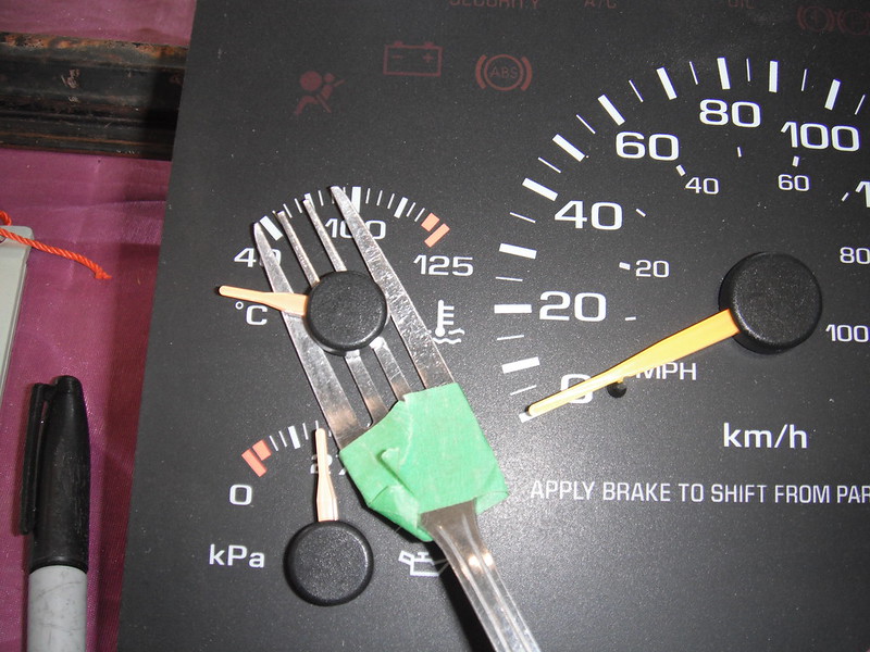 Once the needle is off, the gauge can be unscrewed by a #8 Torx driver (or some really tiny socket). The screws are some kind of self tapping jobs that hold the gauge into the plastic panel, and they are very slim. Heres an S10 gauge. Its small, and its deeper than the original gauges in the Fargo:  Next I had to figure out how to mount the S10 gauges using the Fargo housings. The old gauge faces were incompatible with the new gauges. The Fargo gauges are mounted upside down (the needles point downwards) and the needles rotate counter clockwise. S10 gauges (and pretty much all others) point up and rotate clockwise. Here is an original gauge panel:  And here is how the original gauges and panels went together:  I got a piece of plastic (no idea if it's plexiglass or lexan) and cut it to fit the shape of the back of the gauge housings. After a ton of very careful measurements I was able to drill out holes for the gauge needle shaft and for the self tapping screws (they need starter holes or you will snap them). The drill bit for the self tapping screws was so small that it would not hold in any chucks I had, so I ended up putting the bit in a dremel with an extra small collar. The gauges could now be affixed to the rear of the housings. Heres one of them temporarily screwed in place:  For the gauge faces I could have cut up the S10 panel and tried to use those, but I wanted something that looked a little more period-correct. I took a bunch of measurements and then enlisted my wife to help me out with decals. She is a whiz on the computer and after a couple of hours we had our new faces. We printed them out on paper to let me test the fit, and once I was happy with it we reprinted them on clear, self adhesive label sheets (Avery brand). They worked OK, but they dont print a deep enough black colour. Perhaps Ill try a different brand in the future.The inside of the housing had to be painted, and the original 6 volt bulb replaced with a 12 volt one: 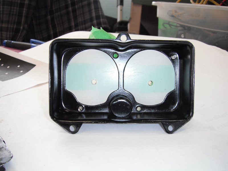 Here is one of the clusters with the lower face sheet in place. The 3 dots align exactly with the S10 gauge high, low and mid points and they sit directly under the needle:  Here is that housing with just the voltmeter installed. To get the needle in the correct spot we grabbed a car battery and tested its voltage, then hooked up the gauge and set the needle to correspond to the reading we got on the battery. Attaching these needles is simply a matter of pressing them onto the shaft (no tools required).  Another decal then gets placed on a thin sheet of plastic that covers the housing, and this sheet labels the gauge. The Fargo housing cover holds this sheet of plastic in place.  When it's all put together it looks like this (only one gauge installed right now as I had not yet gotten to debugging everything).  Next came figuring out how to attach wires to the studs that power the S10 gauges. I was having a tough time finding the special clips that will attach to studs until I posted a query on the 47-59 Board. Another member found them for me (thanks 1project2many !) but they appear either unavailable or out of stock right now and I needed them right away so I had to improvise. I can always switch to the good clips later as I always leave sufficient wire to fix screwups down the line. Heres what we did for now (my son Brian was providing his engineering expertise and its a good thing. He can instantly make out whats happening in a wiring diagram, and he is crazy good at micro soldering). Brian brought up a bunch of these tiny round connectors (neither of us know what they are called), and it turns out that they fit nice and snug on the S10 gauge posts:   From this point it was just a matter of wiring up the 2 gauge pods containing the oil/temp/volts/fuel gauges, as well as the new speedo and then adding loom. Each gauge pod has its own connector so that removal is easy.  Next came the Prindle (the PRNDL indicator). It's always nice to be able to tell what gear you have selected, so this unit had to come out of the S10 cluster and into the Fargo. The prindle is run by a big circuit board within the S10 instrument panel, and the best option seemed to be taking the entire thing out and mounting it in a flat spot behind the dash. Heres how we did it. This plug provides the electrical inputs that the pringle needs:  The plug was depinned:  And the plug was attached to quick connects that led to the S10 harness:  The prindle assembly sits in a plastic box that Brian created on a 3D printer. 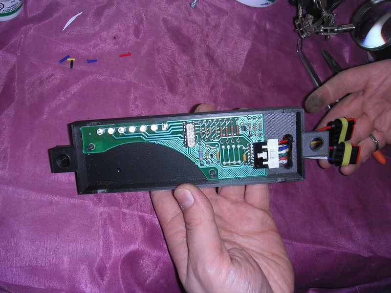 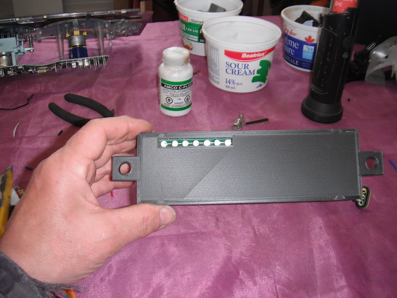 There was a convenient big, empty flat spot on my dash that would easily accommodate the prindle assembly. To mount it I welded 2 studs into the inner face of the dash so that installation or removal just involved loosening 2 nuts and unhooking the quick connector. To be able to see the lighted display I would have to cut a narrow slot into the dash. I was initially reluctant to do this (I hate cutting original antique metal), but then realized how silly this was. Right above the spot where the prindle display slot would sit is a giant hole cut into the dash by some previous owner, and from the quality of the cut I suspect he did his bodywork with a chainsaw. I stopped overthinking things and just got to work cutting the slot into the dash. The hole still needs to be cleaned up, and I have to create some sort of cover that labels the leds that indicate the gear its in.  Heres where it all sits now:  The ring around the speedo has 3 holes for small LED warning bulbs. I had picked up some bulbs but after setting them in place and seeing how they looked I ripped them out (they looked like they belonged in a Honda Civic with a whale tail spoiler and a 4 inch exhaust pipe!). I will find something a little more subtle. After looking at my work, I got to thinking about Gauges model 2.0. I think I will play around with a different design that mounts the gauges deeper into the housings. It will be a little trickier as this obscures the internal light somewhat, but I think I will get a better look that way. I also have to find transparent sheets that can accept black ink better when I print them. For now though I know that I can reuse the S10 gauges, and pulling these out to make them better will be a fun winter project next year. For now I really just wanna go drive this thing. More to follow! |

|

|
| Bookmarks |
|
|


 Threaded Mode