
|
 12-17-2010, 02:25 AM
|
#26 | ||
|
I had a V-8
Join Date: May 2003
Location: Phoenix AZ
Posts: 1,116
|
Re: Berthas Build
Quote:
Quote:
__________________
1972 K20 Suburban, 5.9L Cummins, Banks Power Pack, NV4500HD, NP205, H.A.D., D60/14FF ARB Link To Build: HERE. |
||

|

|
|
12-29-2010, 02:24 AM
|
#27 |
|
Registered User
Join Date: Feb 2010
Location: Dayton, OH
Posts: 255
|
Re: Berthas Build
Alright, time for another update.
I received all of my parts from Cummins so here they are: 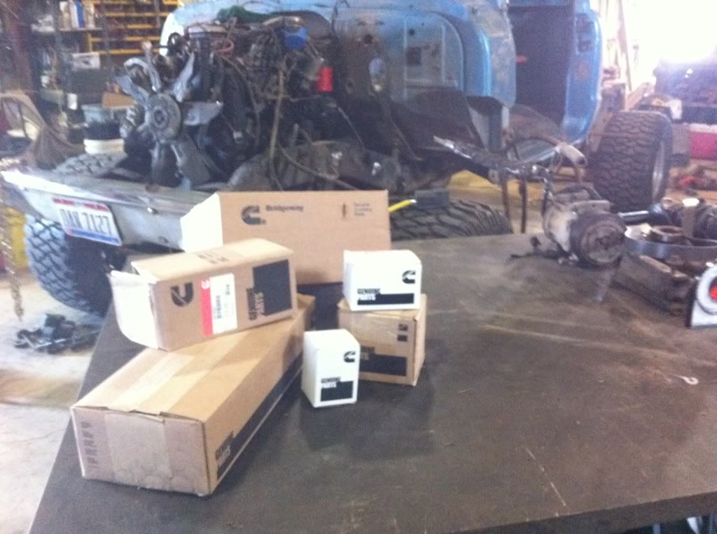 And here they are all layed out: 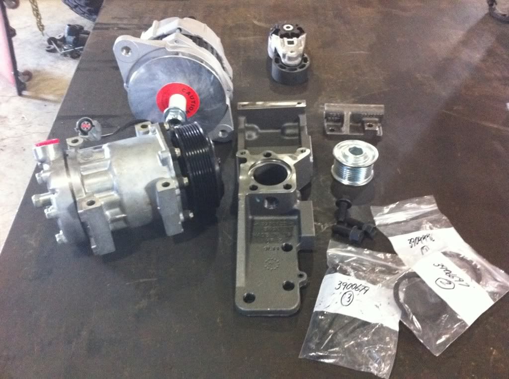 And here they are mounted on the engine: 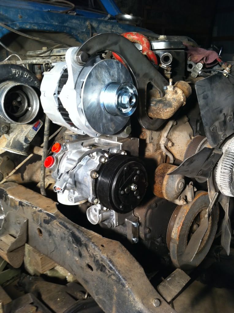 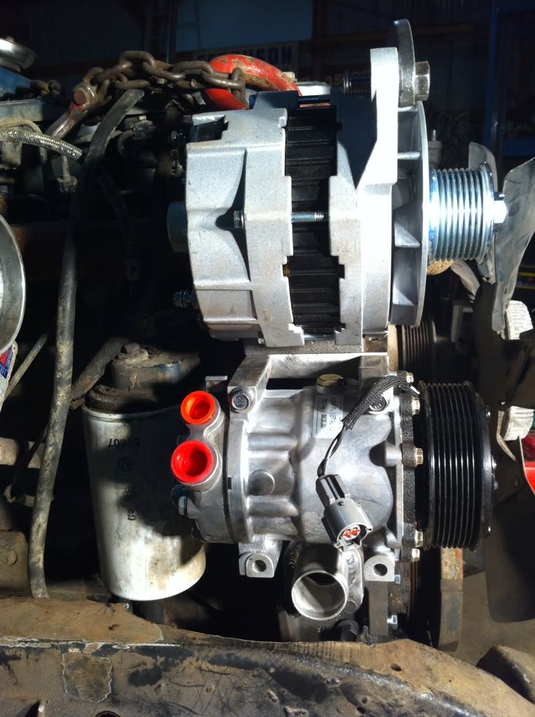  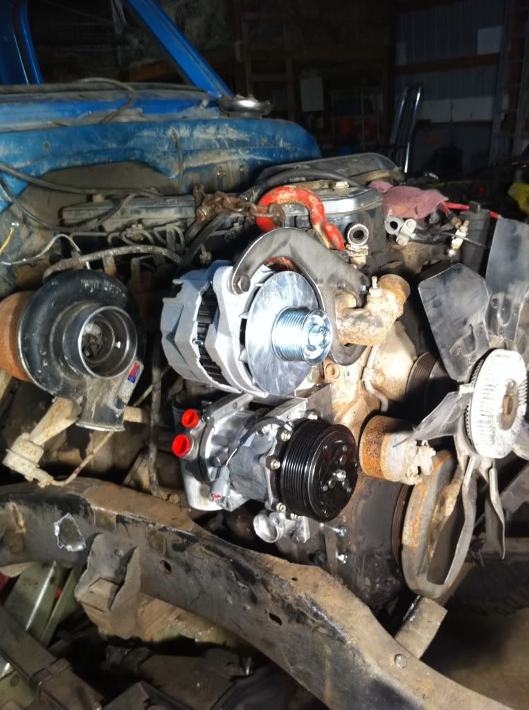 I have a couple of other things happening with this project at the moment as well. Since I have the A/C compressor relocated, I can go ahead and figure out the hydro boost unit as well as the radiator so that I can get this dang drivetrain mounted in the frame once and for all. I received my 1" aluminum body lift from ORD last week which will allow me to get an accurate feel for where my cab/firewall will rest in relation to the bellhousing/back of the engine.  To go with the finding the clearance of the back of the engine and the firewall/trans tunnel, I am also in the middle of some cut and fab so that I can mount my 2nd gen Dodge radiator in my Chevy core support. This is what I started with(minus the two small pieces missing from the top of it) 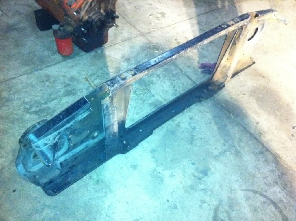 The 71 core support had braces that were perpendicular with the bottom of it as well as flanges that the stock radiator rested against that angle back at the top which in turn angle the stock radiator back about 5 degrees or so. I needed to cut the perpendicular braces to make room for the Dodge radiator but I left the flanges that angle the stock radiator because they do not interfere with the mounting of the Dodge radiator. Cut a little more.....  I welded some 3/16 plate to the locations that the bottom "feet" of the Dodge radiator will rest into. It is not easy welding 3/16 to that sheetmetal! 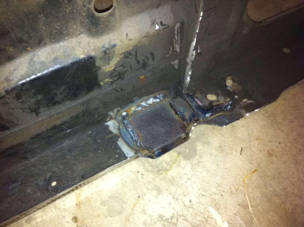 I drilled a 1" hole in each of the mounting pads for the rubber feet of the radiator to rest into. I also created an extension of the support where I had the two sections cut out at the top of the core support. These will be for the two top mounting tabs to have a solid place to mount. They will be finished to create a stock look. 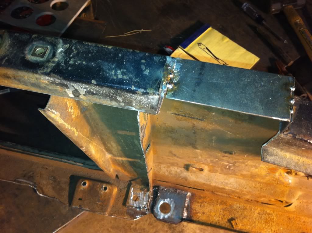 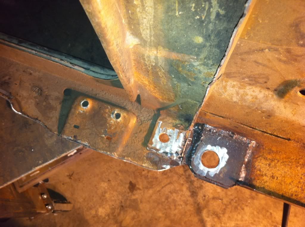 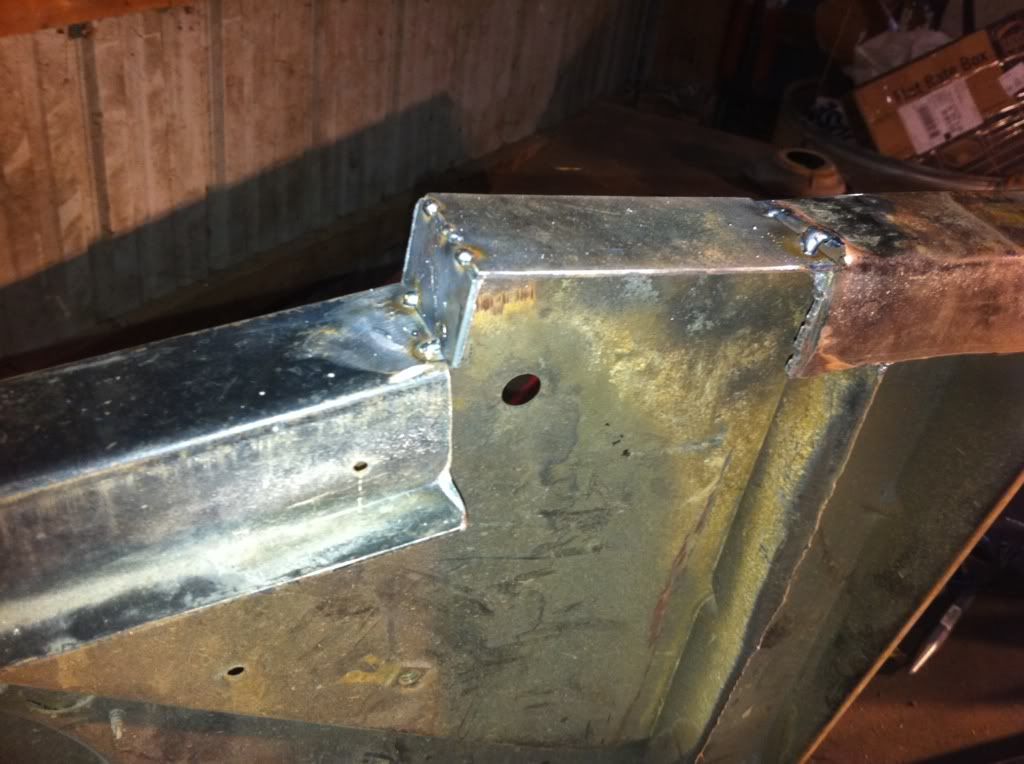 Here are a couple of looks to get a feel for the way the Dodge radiator will mount in the 71 core support. It will be angled back as the stock radiator was although at a bit less of an angle. 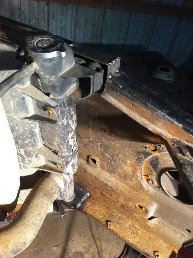 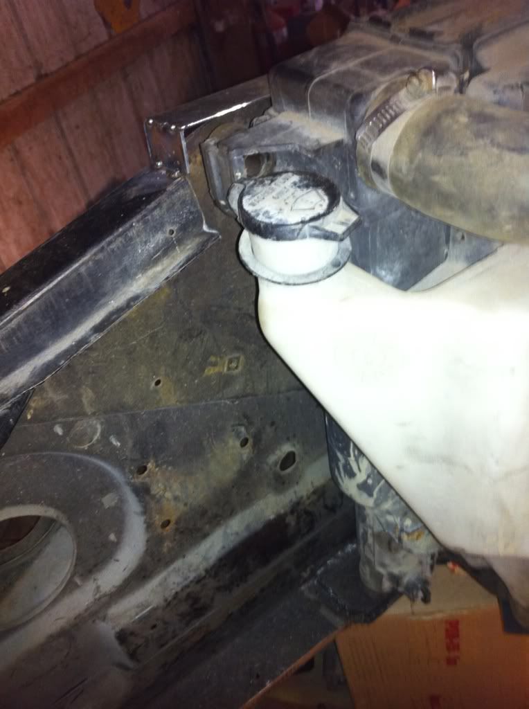 I was planning on using the stock 2nd gen Dodge intercooler as well but it has proven very difficult to get a clean appearance fit to the core support out of it. I will deal with this once I get the past the radiator mount, hydroboost, and engine mounts finalized as it is not critical to the placement of the drivetrain at this point. I also just received my hydroboost unit out of a 1991 C3500 as well as my 2wd steering box out of an 80-87 square body to run my crossover setup. I was able to get everything off of the 91 that was related to the hydroboost, including the lines the Mosesburb and I were talking about. This should make having custom lines made a bit easier to give them the ends and the lengths and have the hydraulic specialists make them. I will have to get the hydroboost mounted to the cab and get the cab set in place once again to check the clearances of the hydroboost and the intake plenum above the injection pump. 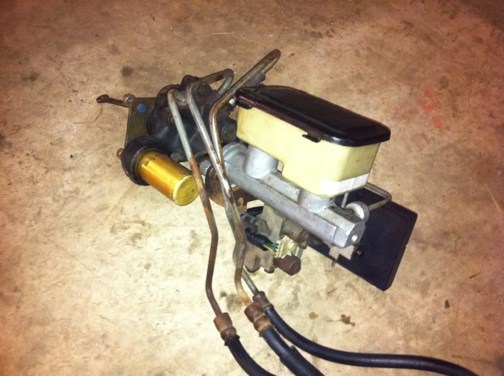 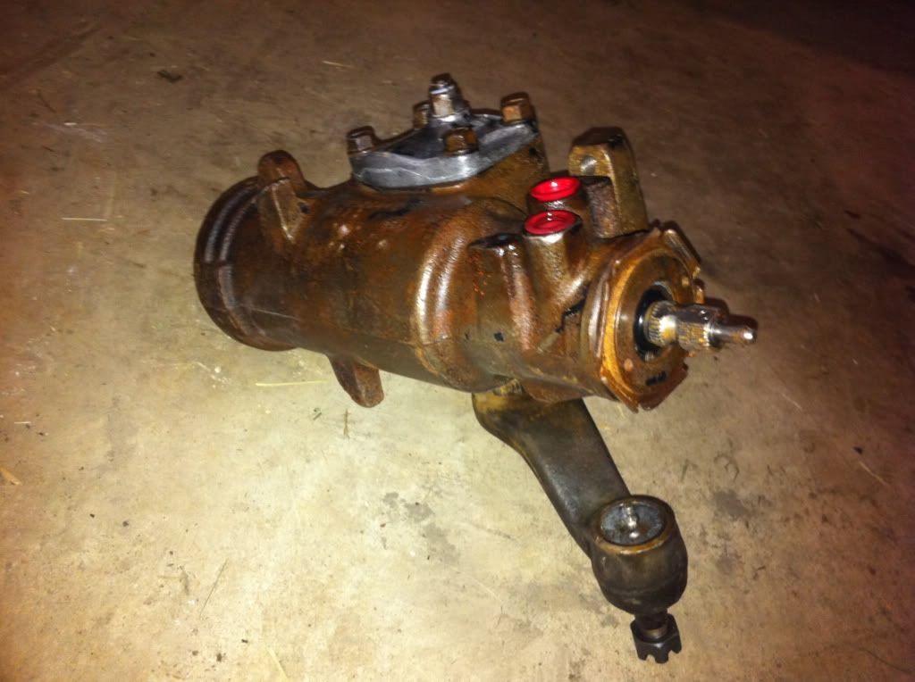 Mosesburb, did you invert the mounting plate on the hydroboost so that it would line up with the hole in the firewall for the brake pedal rod? It looks like if I did this that it would line up better so that I wouldn't have to cut another hole for the rod. I just took a minute to look at the mounting of the hydroboost, so I could be missing something. Here is what I am talking about; you can see the rod hole in the firewall is towards the bottom two studs where as the rod on the hydroboost unit is towards the top two studs: 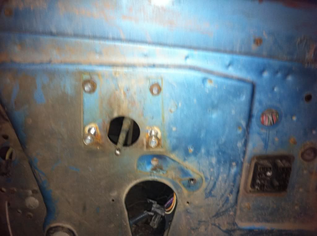 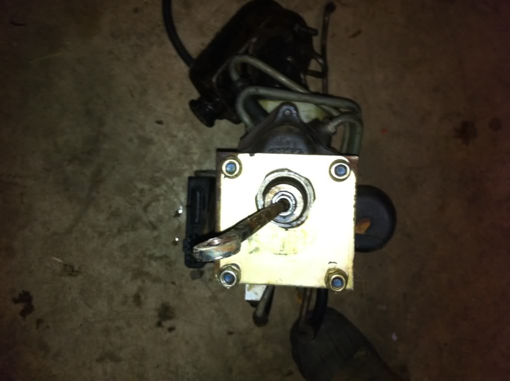
|
|
|
|
|
12-29-2010, 02:36 AM
|
#28 |
|
Chevy Enthusiast
Join Date: Jul 2009
Location: Canyon Lake Texas
Posts: 2,024
|
Re: Berthas Build
Nice progress!
Did you have to cut that notch out of the frame? Can you loosen that nut on the back of the hydra boost and flip over that bracket?
__________________
Tony 1985 GMC K2500 restoration Project: Rust, White & Blue 1989 Chevy R3500 CC Cummins & 4X4 swap some day... 1989 Burb (D60, 14BFF, 12V, NV4500, NP205, 37" tires in progress) |
|
|
|
|
12-30-2010, 02:11 AM
|
#29 |
|
I had a V-8
Join Date: May 2003
Location: Phoenix AZ
Posts: 1,116
|
Re: Berthas Build
I like the core support!! I like how you modified it. It looks like it should work well. On the pieces that you added to the top of the core support, you added a piece of steel that drops down to the original top of the core support. These end at the top of the c/s. If possible, can they be made longer and tie into the rolled edge?? That would add some nice structural integrity back into the area you cut up.
It looks like you are going to have a fun time getting your lower hose out of the confines of the frame rail. I may have to re-visit that area on my truck. It looks like I need to add some room for the hose, but there is no room to add..... On the hydroboost, yeah, knock the studs out and flip the bracket. One set of bolt holes will line up, the other two you will mark and drill and you're done with the plate. The hole in the firewall will have to be opened up a few thou to fit the nut that holds the plate on h/b. I put some RTV on the plate around the nut to seal it when it is installed. Don't use too much or you will never get it off. Trust me on this one--seriously. So where is the tensioner bracket??
__________________
1972 K20 Suburban, 5.9L Cummins, Banks Power Pack, NV4500HD, NP205, H.A.D., D60/14FF ARB Link To Build: HERE. |
|
|
|
|
12-30-2010, 04:58 PM
|
#30 | |||||
|
Registered User
Join Date: Feb 2010
Location: Dayton, OH
Posts: 255
|
Re: Berthas Build
Quote:
That is what I plan on doing with the hydroboost. Mosesburb did this with his Suburban. See ^^^ Quote:
Quote:
Quote:
Quote:
|
|||||
|
|
|
|
12-30-2010, 11:17 PM
|
#31 |
|
Registered User
 Join Date: Sep 2003
Location: DFW
Posts: 765
|
Re: Berthas Build
FYI, for hoses there is the option of using adapters and then having AN lines made up.
here is one source for the adapters: http://www.smileysracing.com/cat/vie...91783&pgID=859 they have the 18MM and 16MM adapters, I have used them with custom hoses many times before However as stated before the ability to walk in to any parts store and get off the shelf parts is ......priceless. Good luck and love the build |
|
|
|
|
12-31-2010, 05:45 PM
|
#32 | |
|
Registered User
Join Date: Feb 2010
Location: Dayton, OH
Posts: 255
|
Re: Berthas Build
Quote:
That is definitely a possibility at this point. That would probably be the easiest way out. Thanks for the compliments too. Posted via Mobile Device |
|
|
|
|
|
01-01-2011, 01:15 AM
|
#33 | |
|
I had a V-8
Join Date: May 2003
Location: Phoenix AZ
Posts: 1,116
|
Re: Berthas Build
Quote:
Definitely a viable possibility. With all the crap I went through on mine getting hoses to work, I probably should have done this myself. I guess I chose that moment in the project to save a few bucks. Go figure. 
__________________
1972 K20 Suburban, 5.9L Cummins, Banks Power Pack, NV4500HD, NP205, H.A.D., D60/14FF ARB Link To Build: HERE. |
|
|
|
|
|
01-06-2011, 10:37 AM
|
#34 | |
|
Registered User
Join Date: Feb 2010
Location: Dayton, OH
Posts: 255
|
Re: Berthas Build
Quote:
Also, how did you figure out the correct length for the pushrod that connects to the brake pedal? I got the hydroboost bracket flipped, drilled the bottom 2 holes in the firewall and the pedal assembly, opened the hole in the firewall for the retaining nut, and mounted the hydroboost on the firewall. Now I believe the only things left with the hydroboost is to figure out what I am going to do with the lines, figure out the right length for the rod that attaches to the brake pedal, figure out if the proportioning valve that came with this hydroboost unit will work for my application, and plumb all of my brake lines. I think that I have a list everything if I don't end up trying to use stock hoses If I go with the AN route for the hydroboost lines, these are the parts I believe I will need: Adapter from 18mm w/o-ring to -6AN Adapter from 16mm w/o-ring to -6AN High Pressure AN Line from pump to hydroboost High Pressure AN Line from hydroboost to steering box Low Pressure Line(either AN for appearance or just rubber hose) from hydroboost return to pump Same as above for steering box return to pump T-fitting to join the two return lines I believe that everything is there. If I am missing something feel free to post it. Now I just need to source this stuff and figure out the right sizes for the return hoses and T-fitting. What kind of hose can I use for the return line and T-fitting? I just mocked up my engine crossmember and motor mounts Tuesday night and I will begin welding them in tonight along with fabricating a crossmember to use with the stock transmission mount. Finally, no more blocks, jackstands, jacks, chains, or hoist locating it in the frame rails! I will get pictures up when I am finished with the transmission crossmember hopefully tonight or tomorrow night. Last edited by dfairchild19; 01-06-2011 at 10:44 AM. |
|
|
|
|
|
01-07-2011, 02:51 AM
|
#35 | ||||||
|
I had a V-8
Join Date: May 2003
Location: Phoenix AZ
Posts: 1,116
|
Re: Berthas Build
Quote:
Quote:
Quote:
You say you drilled two holes in the firewall. I drilled the other holes for the studs that stick out of the firewall in the hydroboost plate. IIRC, the lower holes would interfere with the column mounting bracket that bolts to the firewall. Maybe not?? Again, its been awhile. Quote:
I would still consider having the hoses made up. You should be able to have them put the fittings and ferrules on the ends of your steel factory lines, buy approximately the right amount of hose, bring it home, mock up the lines so they fit right, mark the position of the hose to the ferrules with a Sharpie, remove everything from truck, take to hose making establishment and have them finish the assemblies by crimping the ferrules in the position you have them marked as. A little brake clean on a rag takes the remnants of the Sharpie off and you're done. Quote:
Quote:
__________________
1972 K20 Suburban, 5.9L Cummins, Banks Power Pack, NV4500HD, NP205, H.A.D., D60/14FF ARB Link To Build: HERE. |
||||||
|
|
|
|
01-07-2011, 03:21 AM
|
#36 |
|
Registered User
Join Date: Sep 2010
Location: ND
Posts: 520
|
Re: Berthas Build
Sweet build! Signing up to see how to do my build.
__________________
Name: Les ---------------------- Couple 80s Couple 70s One 68 
|
|
|
|
|
01-21-2011, 12:44 AM
|
#37 | ||
|
I had a V-8
Join Date: May 2003
Location: Phoenix AZ
Posts: 1,116
|
Re: Berthas Build
Quote:
As far as the rod goes, I took the rod that the hydroboost came with and cut the pedal end ring off of it. For the pedal end I took a 73-? female threaded booster rod end and bored it out to a slight press fit on the o.d. of the cut off hydroboost rod. I put it all in the truck, set the pedal 1/2" off the rubber bumper, marked the location on the hydroboost shaft, pulled it all out and welded it together. I'm not a big fan of welding on brake parts, but I figured the part is piloted into the female end and the weld will only be in compression, not tension and there will be no real side-loading. With that going for it, I decided that was my way out of that situation. Quote:
Oh, wait, :yawn:
__________________
1972 K20 Suburban, 5.9L Cummins, Banks Power Pack, NV4500HD, NP205, H.A.D., D60/14FF ARB Link To Build: HERE. |
||
|
|
|
|
01-24-2011, 06:42 PM
|
#38 | ||
|
Registered User
Join Date: Feb 2010
Location: Dayton, OH
Posts: 255
|
Re: Berthas Build
Quote:
Quote:
 Any time that I do get to myself right now is time spent running out to the barn real quick to clean up or to see if something possibly got accomplished while I wasn't there! Spring will be here eventually and that is when the real work will begin. Last winter I didn't even have the motivation to turn a wrench let alone spend hours fabricating and making this darn thing fit where it shouldn't. So the way I see it, anything that gets accomplished in the winter in that freezing barn puts me that much further ahead than I could hope for in the winter to be ready for the real progress in the spring. Stay posted, the updates will come before you know it. Any time that I do get to myself right now is time spent running out to the barn real quick to clean up or to see if something possibly got accomplished while I wasn't there! Spring will be here eventually and that is when the real work will begin. Last winter I didn't even have the motivation to turn a wrench let alone spend hours fabricating and making this darn thing fit where it shouldn't. So the way I see it, anything that gets accomplished in the winter in that freezing barn puts me that much further ahead than I could hope for in the winter to be ready for the real progress in the spring. Stay posted, the updates will come before you know it.
|
||
|
|
|
|
01-24-2011, 11:36 PM
|
#39 |
|
Registered User
Join Date: Feb 2010
Location: Parsons, KS
Posts: 357
|
Re: Berthas Build
I've been considering boxing the frame on my truck also and i have a couple questions if you dont mind.
1. can you only box the parts of the frame that you did? 2. Are you going to seal the parts off that you boxed so that they dont hold moisture or leave them open on the ends? 3. how thick of metal did you use? 4. do you have any more pictures of the process? Thanks James
__________________
James 94' Chevy K1500 Extended Cab 4x4 5.7 72' Chevy LWB K10, 350, SM465, NP205 Project "Daily Driver" |
|
|
|
|
01-25-2011, 01:12 AM
|
#40 | |
|
Registered User
Join Date: Feb 2010
Location: Dayton, OH
Posts: 255
|
Re: Berthas Build
Quote:
1. I wouldn't. If only the parts that I boxed are done, it will leave the sections between, behind and in front of those areas weaker making them take all of the stress and forces. 2. I am going to seal it off as much as I can so that the only way that moisture will be able to enter the inside of the frame is if it is submerged. I am still going to try to prime and paint the inside of the frame and boxing plates but I am sure there will be some areas exposed from being burnt from the welding. 3. I believe it was 3/16". 4. I might have some more of the mock up process but you will see more of this when I pull the drive train and do final weld in of the motor mounts and the final weld in and completion of the frame boxing. Good luck with your project and if you have any questions feel free to ask. |
|
|
|
|
|
01-25-2011, 09:02 AM
|
#41 | |
|
Registered User
Join Date: Feb 2010
Location: Parsons, KS
Posts: 357
|
Re: Berthas Build
Quote:
__________________
James 94' Chevy K1500 Extended Cab 4x4 5.7 72' Chevy LWB K10, 350, SM465, NP205 Project "Daily Driver" |
|
|
|
|
|
05-25-2011, 11:50 PM
|
#42 |
|
Registered User
Join Date: Feb 2010
Location: Dayton, OH
Posts: 255
|
Re: Berthas Build
Alright. I have been way too wrapped up in the build and working on it to post all of my progress in my build thread. Looking back I wish I would have taken the time to post progress as I completed it mainly so that I didn't have to do what I am doing now and posting all of it at once. Also, so that I could have had the input and therefore the motivation from all of the members of the board.
So here it is now, your not-so record setting thread update. I believe it was right at 5 months ago since the last post to this thread so ive got some catching up to do. I am not even exactly sure where it was that i left off last but i will do my best to start where i ended. This will mostly be pictures for time's sake but I will do my best to get back to the thread to add descriptions I am actually dozing off while writing this so I think that I will wait til next time to post the actual good stuff. i dont want to give it all away before i actually post the update but I can say that I have made progress about 3 days a week on average since my last update, with most of it being on the frame. Stay tuned as I have a good 70 pictures to post up with some good progress. Derek |
|
|
|
|
05-26-2011, 02:43 PM
|
#43 |
|
Registered User
Join Date: Feb 2010
Location: Dayton, OH
Posts: 255
|
Re: Berthas Build
Ok, so I believe that my last update had to do with positioning the drivetrain within the frame, mounting the high mount a/c setup, and modifying the core support to accept the Dodge radiator.
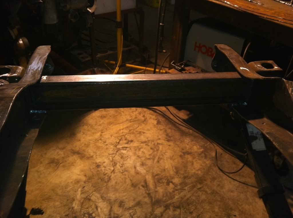
The drive train has found its final resting position, the high mount a/c setup has obviously been mounted, the core support is near complete(minus modification for the intercooler cutouts), plus tons more. I would be willing to bet I've put in over 100 hours since the last update. The unfortunate thing is that I say Ive got that much time into it but one might expect more progress than I have. I will let you be the judge of that. I believe that the next thing that I completed after I left off was the engine crossmember. I bought it from a member on another board. I was going to build my own but the design that he had was really close to what I had envisioned and the measurements and work was all completed for me. The only thing I had to do was modify it to fit my frame where i wanted it in the frame rails and weld it together and weld it in. 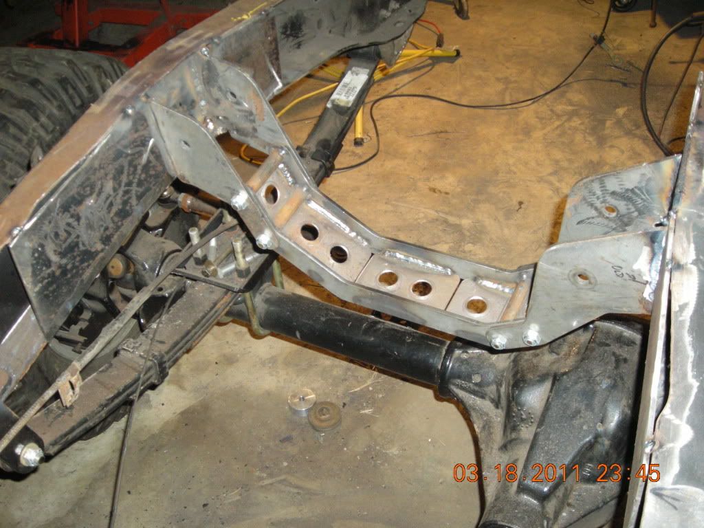  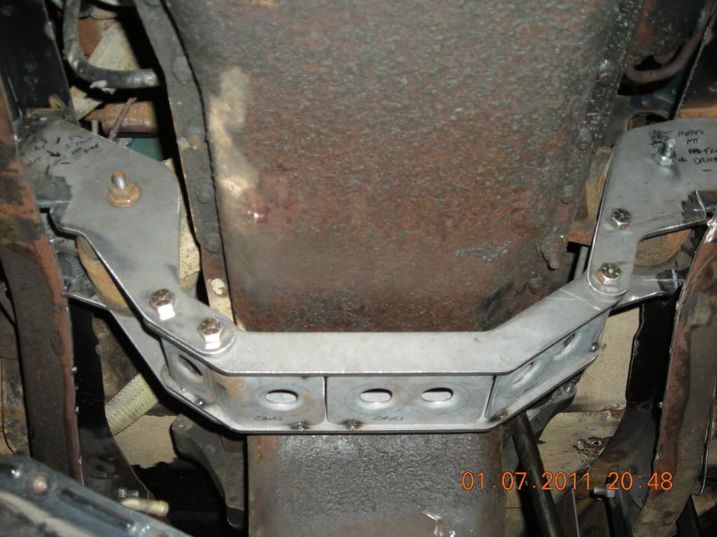   After I modified and finished the Engine crossmember and mounts, I moved to the transmission mount and crossmember. I ended up using the stock 2wd(not sure if it is universal to 4wd) rubber mount from the Dodge tranny. I will have to modify it by cutting off the exhaust hanger as it will be right in front of the front output of the transfer case. Once I had the vertical location of the rear of the drivetrain, I centered it in the frame rails and build a crossmember around it. The crossmember itself is more 2x4 3/16" box tube and the brackets are 1/4" plate cut on the water jet. I sleeved the frame where the 4 bolts of each bracket go through before I built the x member. Two holes for the tranny mount studs in the top of the x member and two oversize holes in the bottom for the washer nuts. Sorry for the poor quality pics. I should be able to leave my camera out in the barn now that it is warmer out. 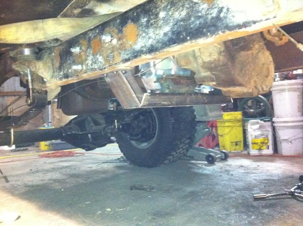 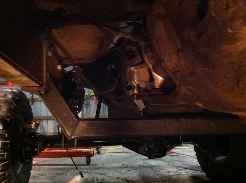  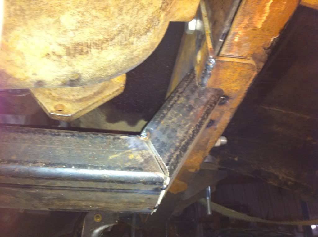 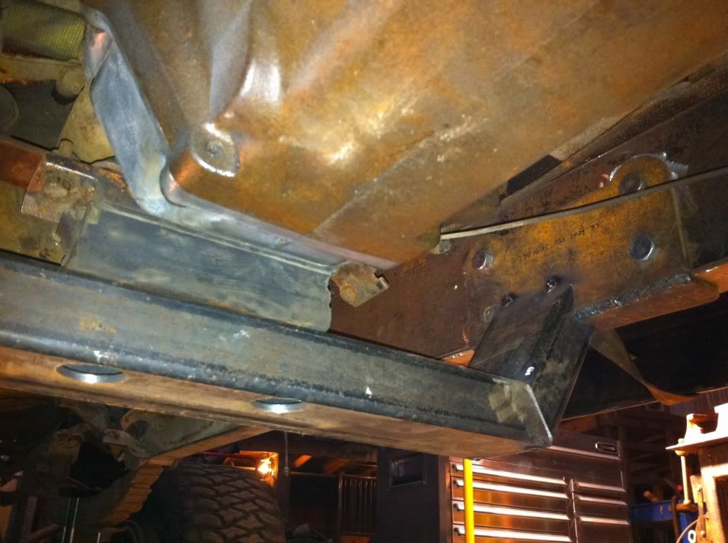 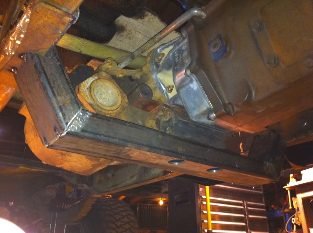 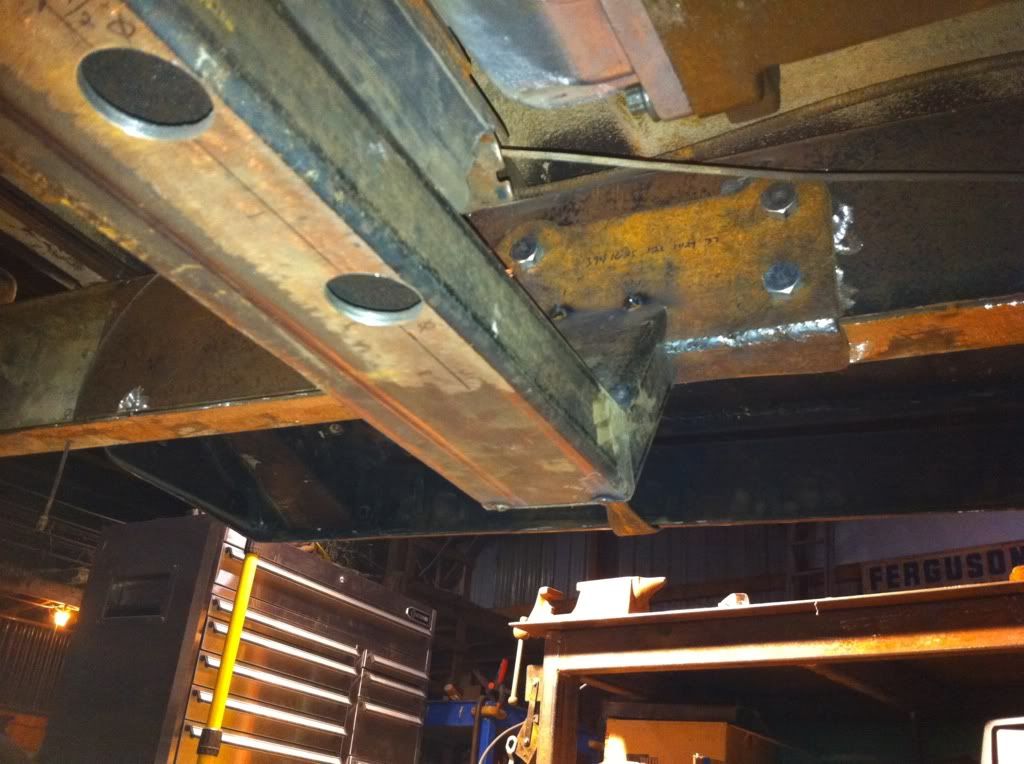 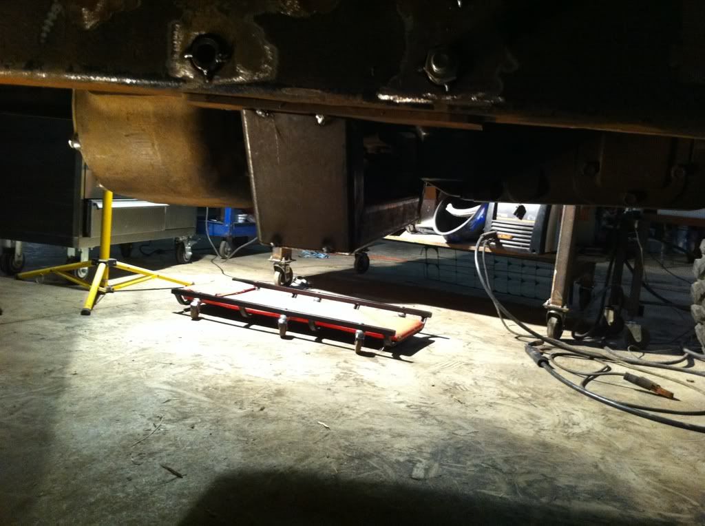  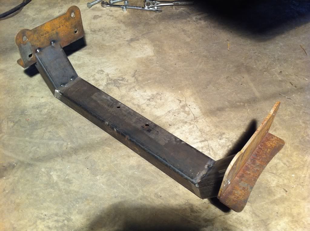 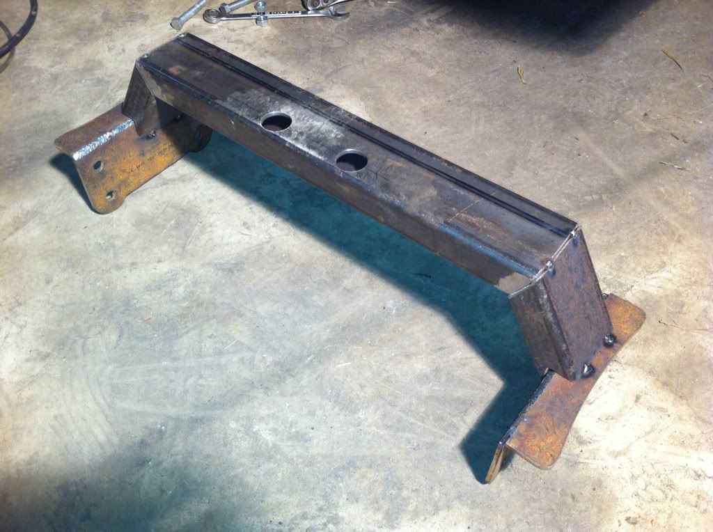
|
|
|
|
|
05-26-2011, 03:31 PM
|
#44 |
|
Registered User
Join Date: Feb 2010
Location: Dayton, OH
Posts: 255
|
Re: Berthas Build
After I finished the tranny and engine x members that I poured hours into, I started on the forward most x member. I had thought about using the stock location for this one but if I did that it would have had to been notched for the cooling fan. So instead of having to notch it, I moved it forward a bit to clear it. I had to notch the ends a bit to slip past the bolts holding on the core support mounts/front spring hanger mounts resulting in not as much surface to weld to but since I am boxing the frame, I should not have an issue here.
 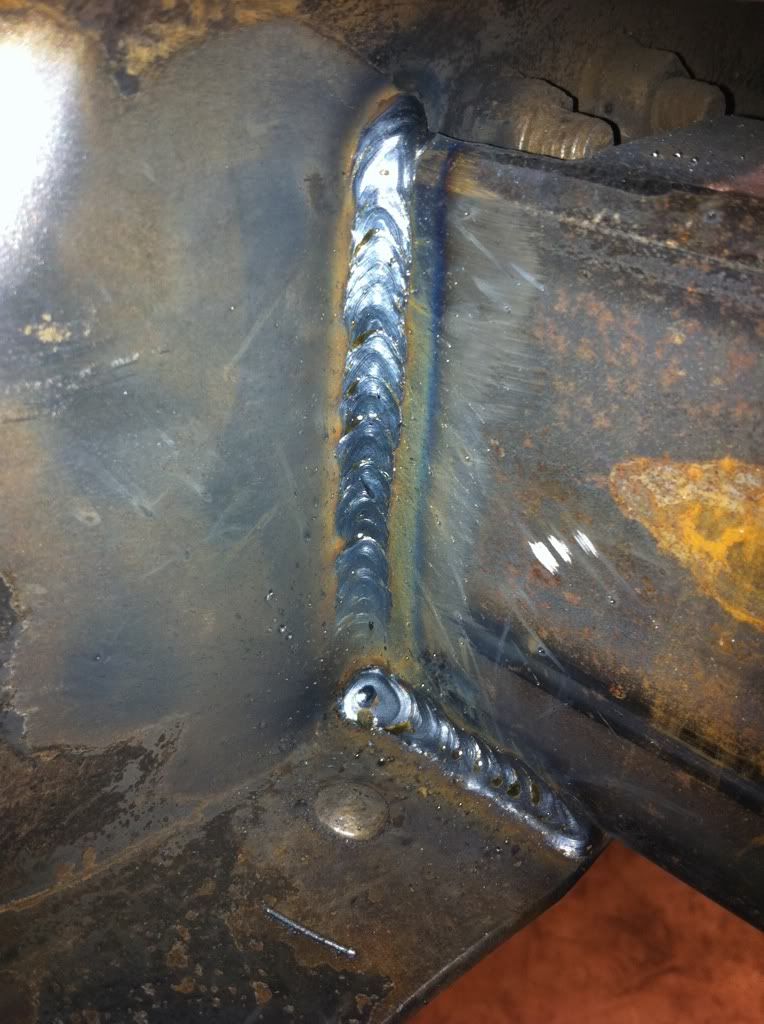 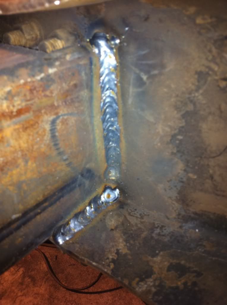 Keeping with the mid-front parts of the frame, after finishing the x members I started on the steering box area as well as clearance for the tensioner bracket, lower water neck, front case cover, and power steering pump. For the steering box mounting, I used the same sleeves as the tranny x member bolt sleeves, bolted the gear box to the frame with the sleeves on the bolts and tacked them in. I then removed the gear box and its bolts from the sleeves and boxed the front portion of both frame rails cutting holes for the steering box sleeves. After some trial and error, I had the driver side all tacked in and ready for final welding of the seams. While I was at it, I notched the corner of the frame a bit for the front gear case of the engine. You can see it in the last few pics of the steering boxing. 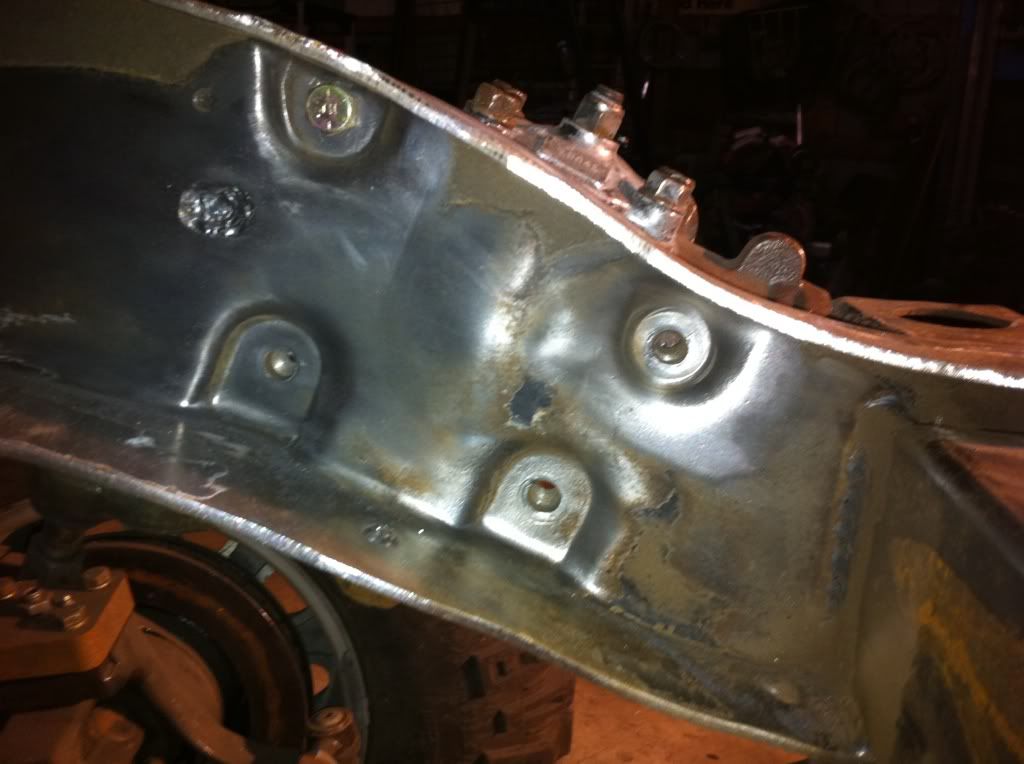 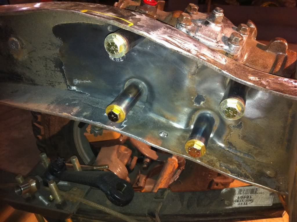 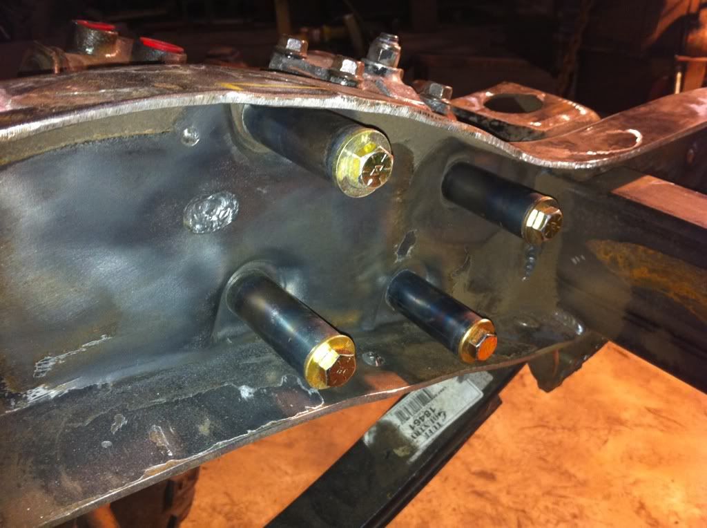 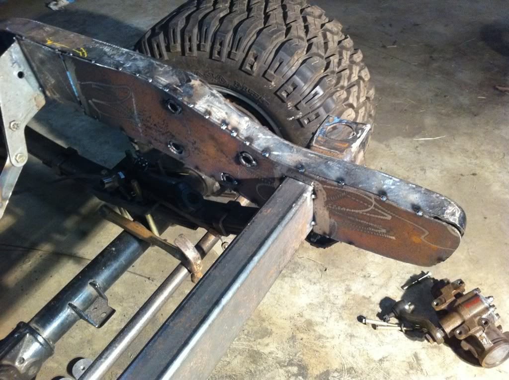  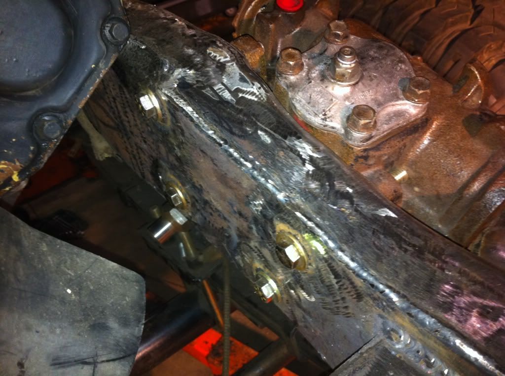 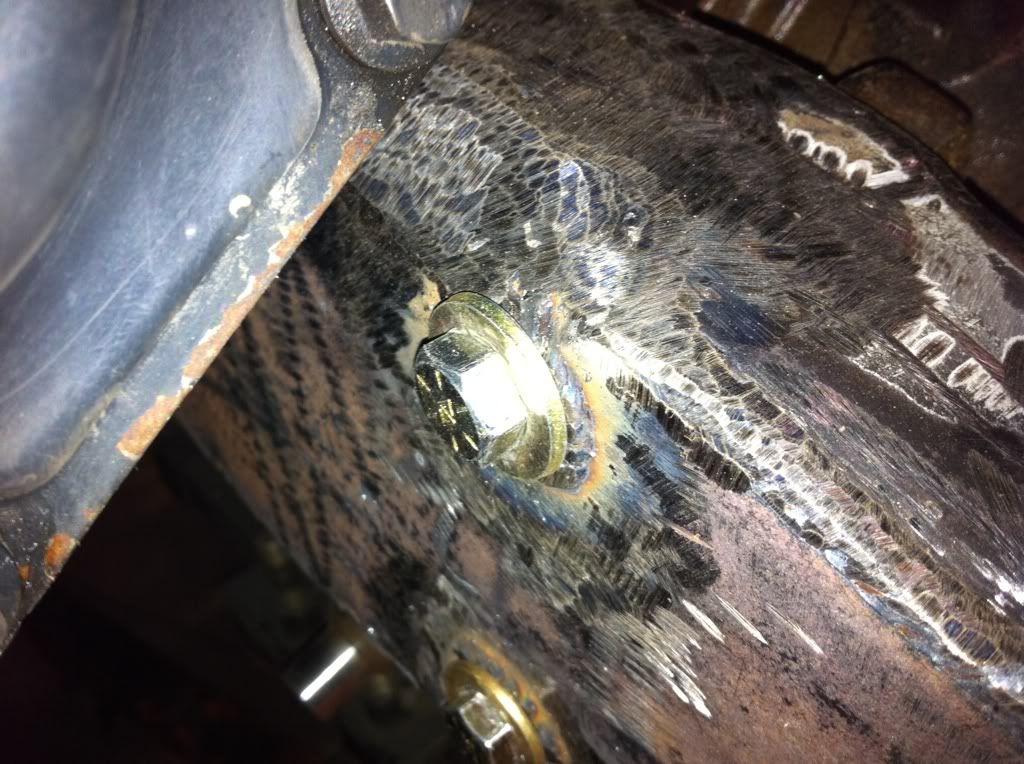  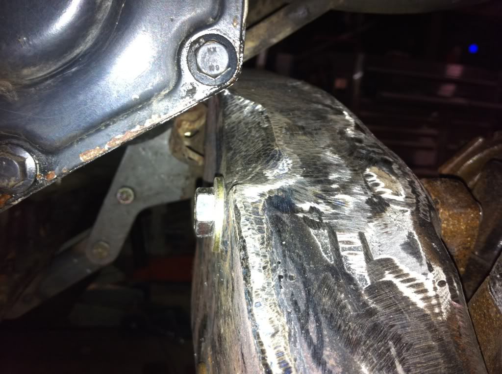 For the passenger side, I had to notch the frame to clear the tensioner bracket as well as the lower water neck. This went surprisingly quick. I cut and weld and cut and weld and it was finished. Pretty straight forward. 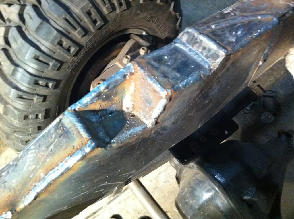 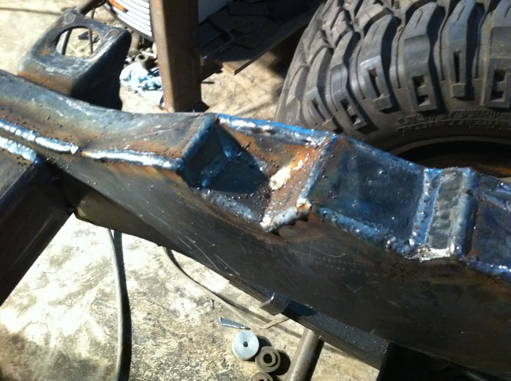 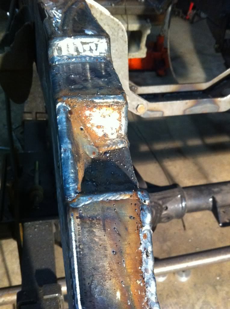 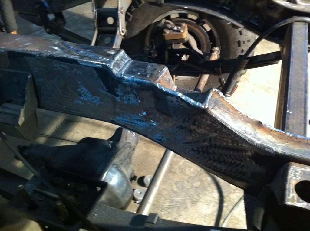  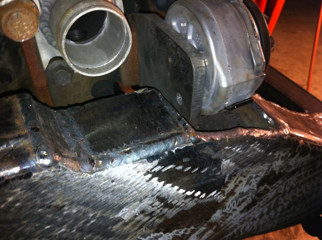 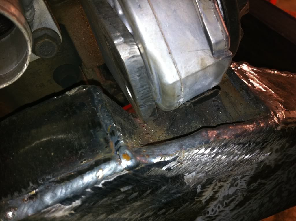 And then just some overall shots of the front of the frame progress: 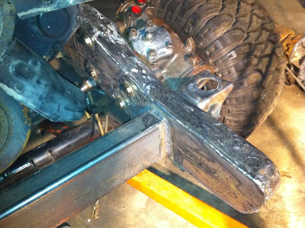 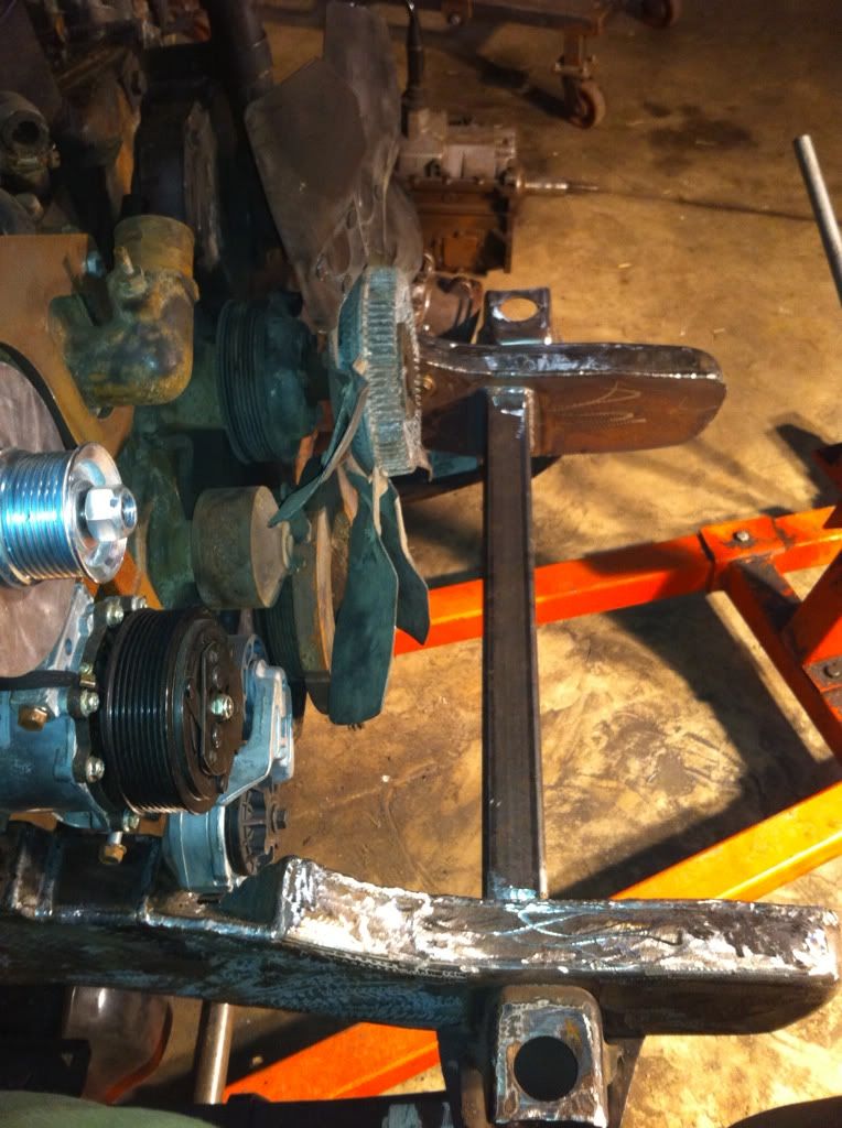 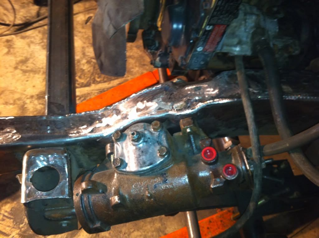 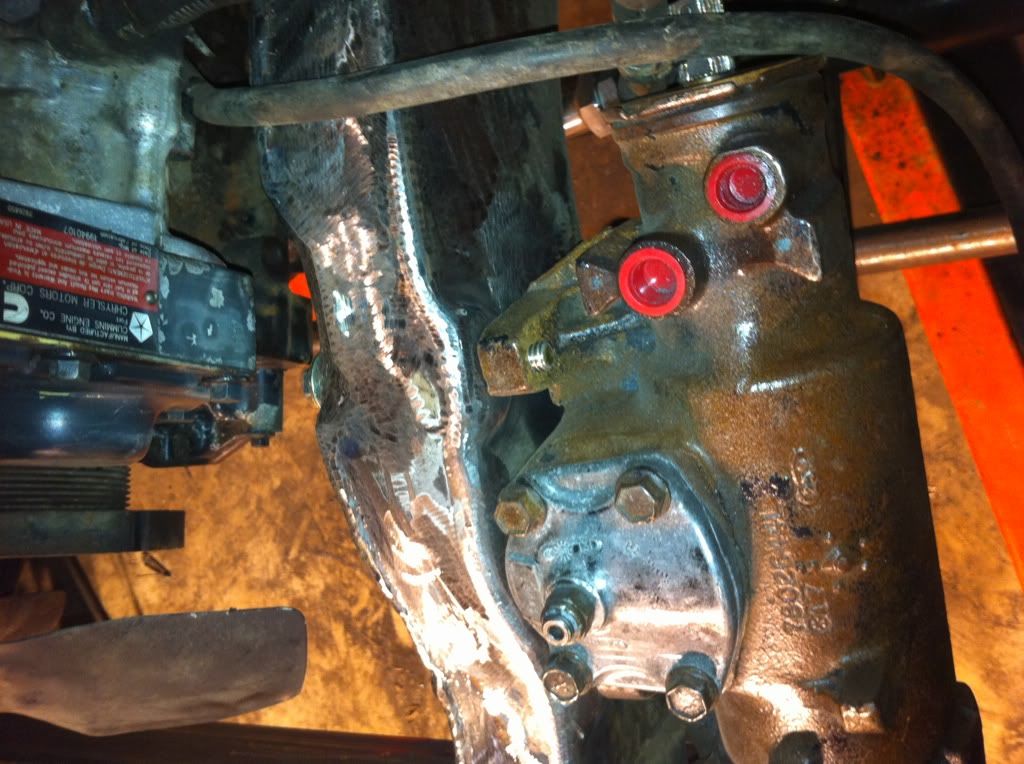 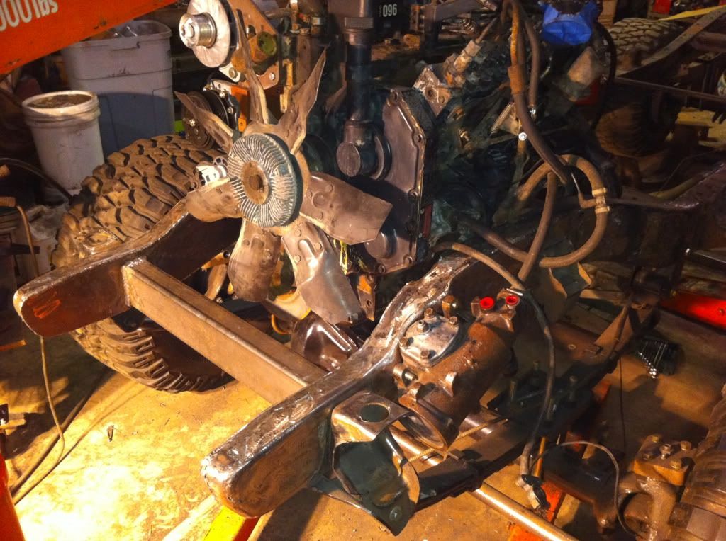 Then some boxing between the x member boxing: 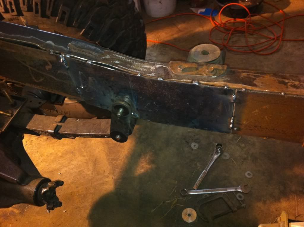 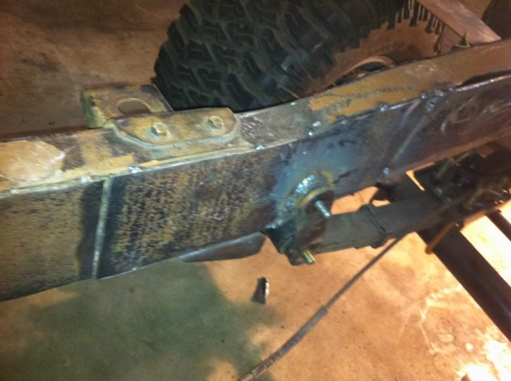
|
|
|
|
|
05-26-2011, 04:22 PM
|
#45 |
|
Registered User
Join Date: Feb 2010
Location: Dayton, OH
Posts: 255
|
Re: Berthas Build
With the front of the frame basically completed, I pulled the rolling chassis forward and migrated all of my tools and workstation to the rear to get started on it. I thought that the rear was going to be much easier than the front because I didnt think that I was going to have to make as many modifications. I learned quick that this was not going to be the case. With more of the same stripping paint and rust, removing rivets, filling holes, building x members, and boxing it definitely wasnt going to be a walk in the park. The things that needed done were not difficult by any means, just terribly time consuming and tedious.
The first x member i did was the one in front of the rear wheels. I removed the old and cut and welded in the new. I then threw in some bracing to make it a bit more stout. 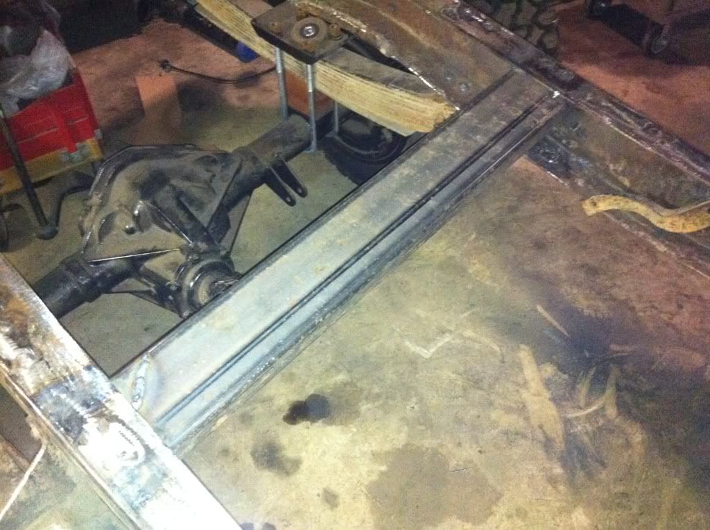 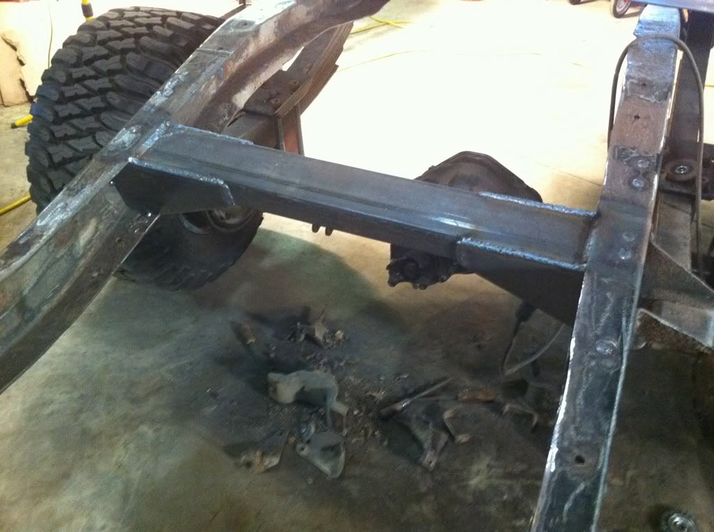 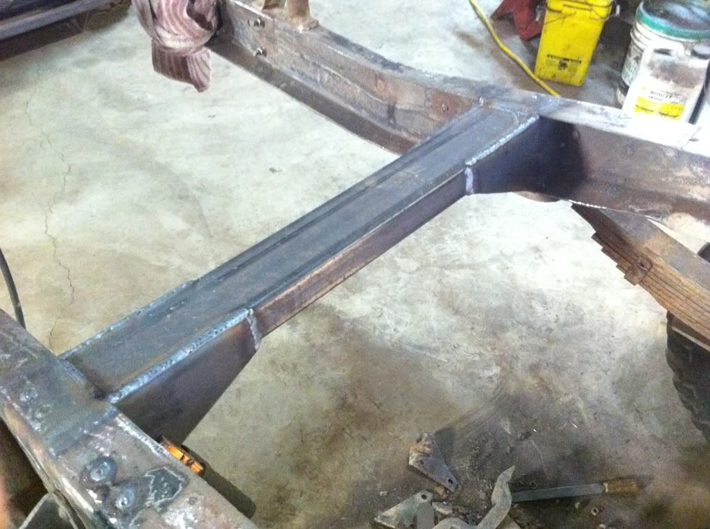 After that I cut the rear most x member and welded it in in the factory position while also sleeving the frame for the rear 2 pairs of bed mounts. 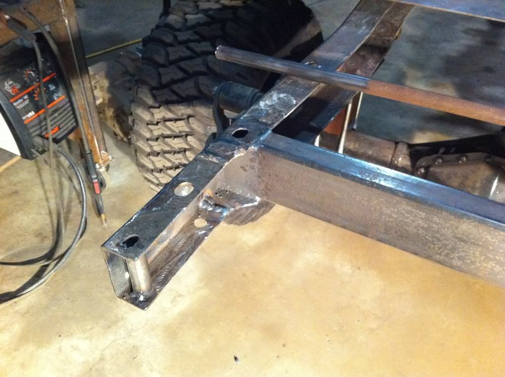 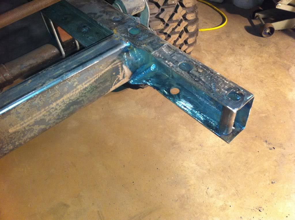 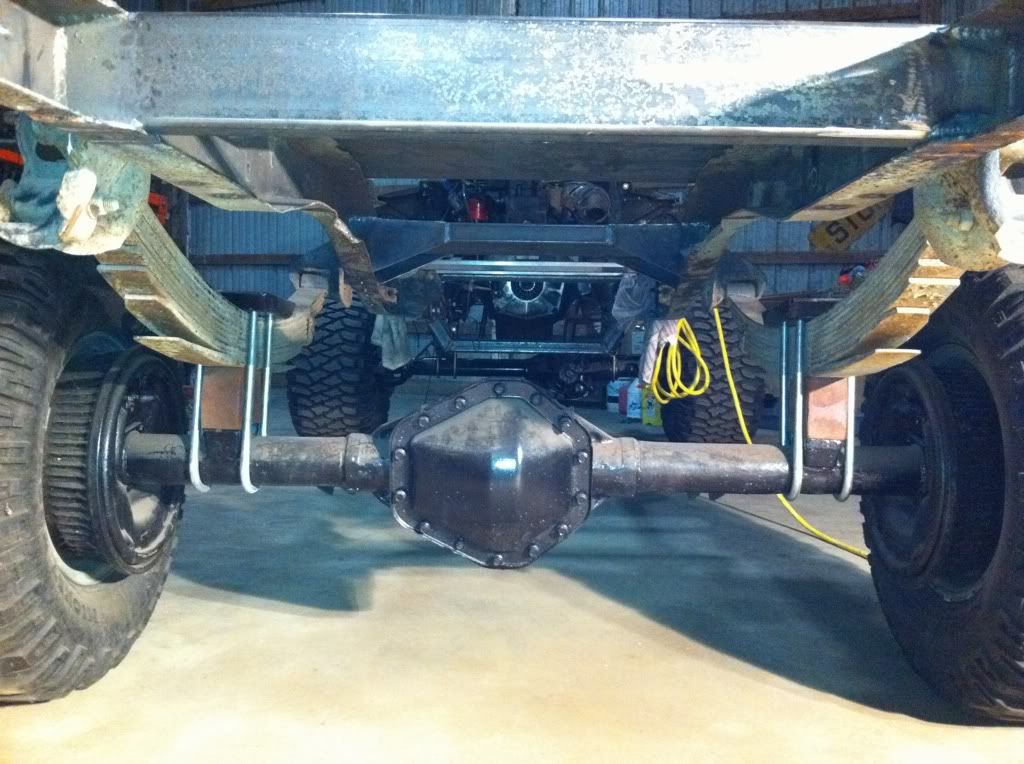 With the exception of the boxing. the rest of the rear portion of the frame just kind of ran together from removing lips and recesses, to filling holes, to sleeving the frame for the rear bumper and hitch mount. 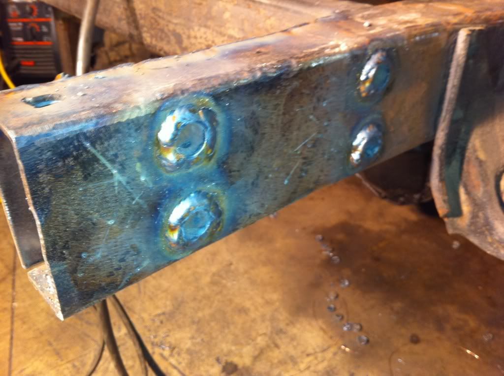 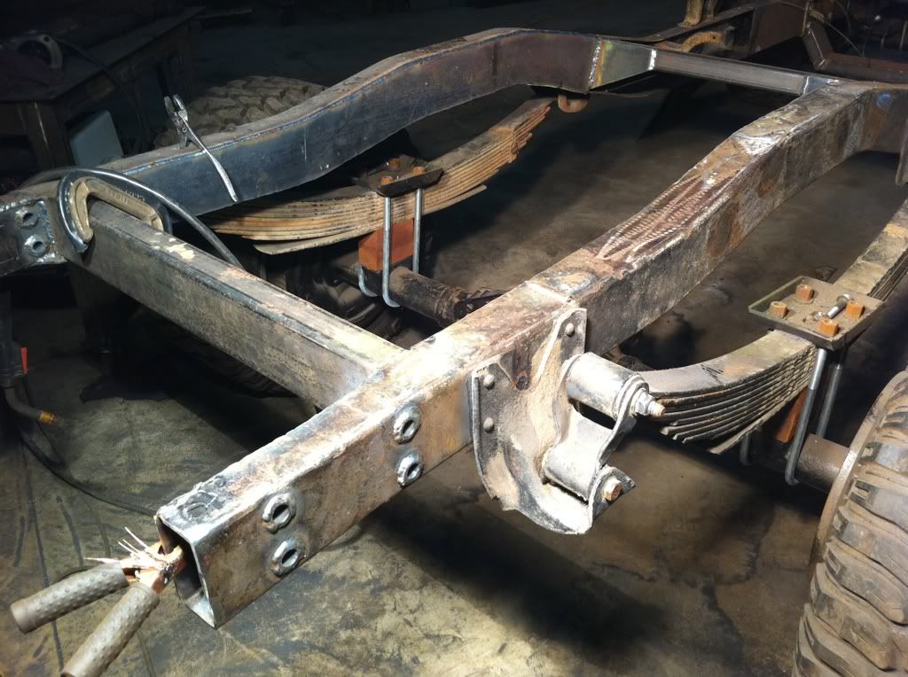 After I finished up the rear section of the frame including the boxing, I removed both axles out from under the frame and got it in good position to finish weld the top and bottom of the boxing. When I finished that, I added some rear upper shock mounts using the factory studs on a pair of plates I cut out. I plug welded the back of the stud to the plate as well as the plate to the frame. Then I fully welded the stud to the plate and then the plate to the frame. 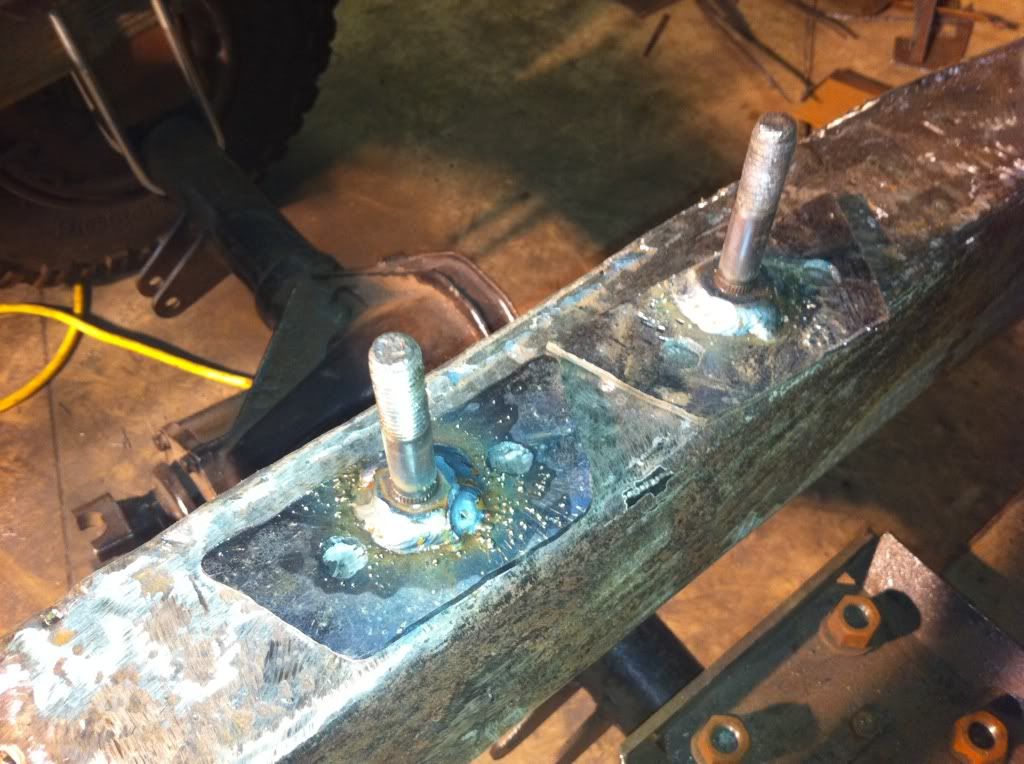 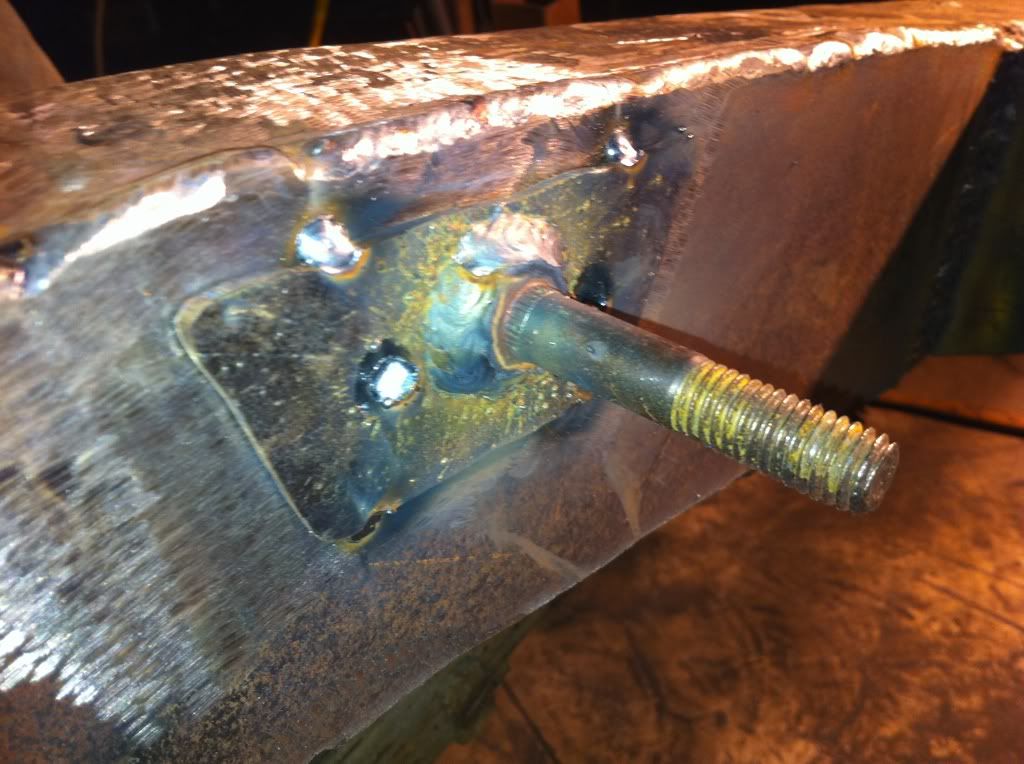 This is how I positioned the frame to give myself good positioning for final welding. 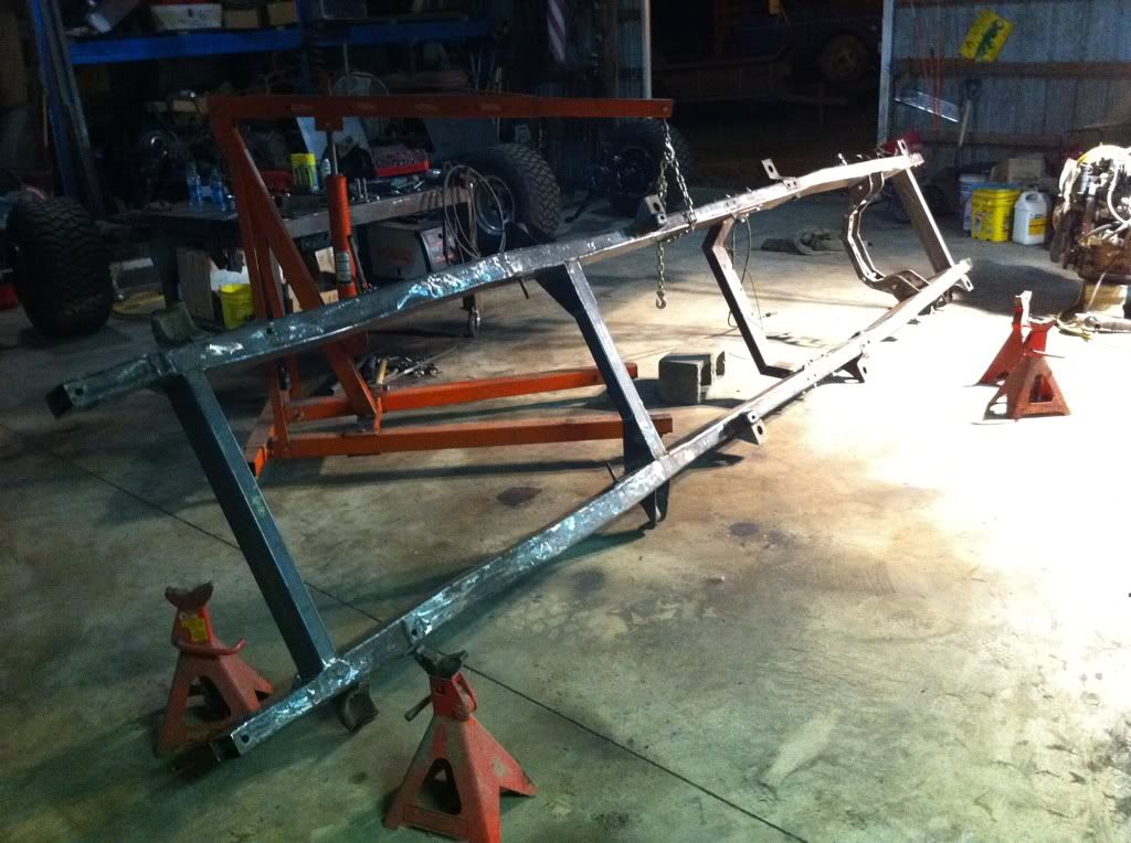 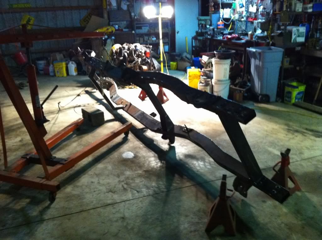 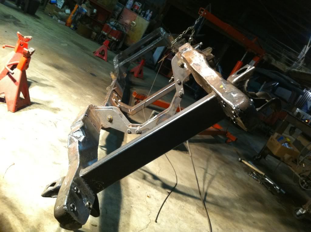 That was one of the last things I did to the frame before I threw the axles back under it to make it a bit more mobile. The last few nights I have been working on getting my sand blaster working well so that I can blast all of the spring mounts and body mounts that I cant get to with a wire wheel or grinder. Right now I am just waiting on a dry day to come along with some time from my fiance to roll it outside to do the sandblasting so that I can get started on painting the frame and rear springs. While I am waiting a dry day, I am also going to start pulling components off of the engine so that I can paint it and the tranny and x case right around the same time I paint the frame. Once all of that stuff is painted and reassembled I can bolt the frame to the springs and axles and bolt the drive train to the frame hopefully for the final time. When the paint and final assembly of the frame and drive train are complete, I will have reached a huge milestone of this project and I think that things will start to move much quicker shortly after that as I will dive into the rust repair of my cab. Keep an eye out as this thing will start to come together in the near future. Derek |
|
|
|
|
05-26-2011, 07:02 PM
|
#46 |
|
Registered User
Join Date: Oct 2007
Location: Spanaway
Posts: 8,451
|
Re: Berthas Build
Nice work!
__________________
Mike. Swamp Rat build thread : http://67-72chevytrucks.com/vboard/s...d.php?t=595019 72 3/4T 4X4 4" BDS Lift 33" BFG's |
|
|
|
|
05-26-2011, 07:17 PM
|
#47 |
|
Registered User
Join Date: Feb 2010
Location: Kitimat, British Columbia, Canada
Posts: 234
|
Re: Berthas Build
I was curious what was happening to this project, it's good to see you are still working on it. Great fabbing skills you have and i really enjoy the route this project is taking. I would like to see my with a cummins, but i have to settle for a BBC instead for now seeing as i got it for free from a friend. I can't wait to see it coming back together.

|
|
|
|
|
05-26-2011, 07:27 PM
|
#48 |
|
Registered User
Join Date: Feb 2010
Location: Parsons, KS
Posts: 357
|
Re: Berthas Build
WOW that frame is looking killer. great work!!!!!
__________________
James 94' Chevy K1500 Extended Cab 4x4 5.7 72' Chevy LWB K10, 350, SM465, NP205 Project "Daily Driver" |
|
|
|
|
05-27-2011, 10:42 AM
|
#49 |
|
Registered User
Join Date: Feb 2010
Location: Dayton, OH
Posts: 255
|
Re: Berthas Build
I appreciate the compliments guys
|
|
|
|
|
06-12-2011, 10:30 PM
|
#50 |
|
Registered User
Join Date: Dec 2009
Location: Orlando, FL
Posts: 131
|
Re: Berthas Build
What did it cost you for all the stuff needed for the mid-mount AC? Im running into the same issue. And i was going to run a vintage air kit. do you know if there is any issue with the compressor compatibility for an aftermarket ac kit?
|
|
|
|
 |
| Bookmarks |
|
|


 Linear Mode

