
|
 03-18-2013, 08:00 AM
|
#1 |
|
Registered User
Join Date: Jan 2013
Location: Leonardtown, MD
Posts: 1,633
|
Fender Patch how-to
I had posted this as a response to another thread, and was asked to post it by itself. Although this was for a car, the lessons apply universally, so here goes..
A couple of years back, I was reading a thread on a first-time fender repair by the owner, and he was looking for some insight as to how he should proceed. He wasn't too pleased with his results, and after a few suggestions, I offered to show him how to do the repair in my shop. He was only two hours away, so it wasn't too far a drive.. Zach showed up in the Biscayne, which really helped out to have a good pattern in the adjacent panels to work against. He was originally going to just bring the fender, but I think after all is said and done we can see that would not have worked as well. Here is what we had to work with. 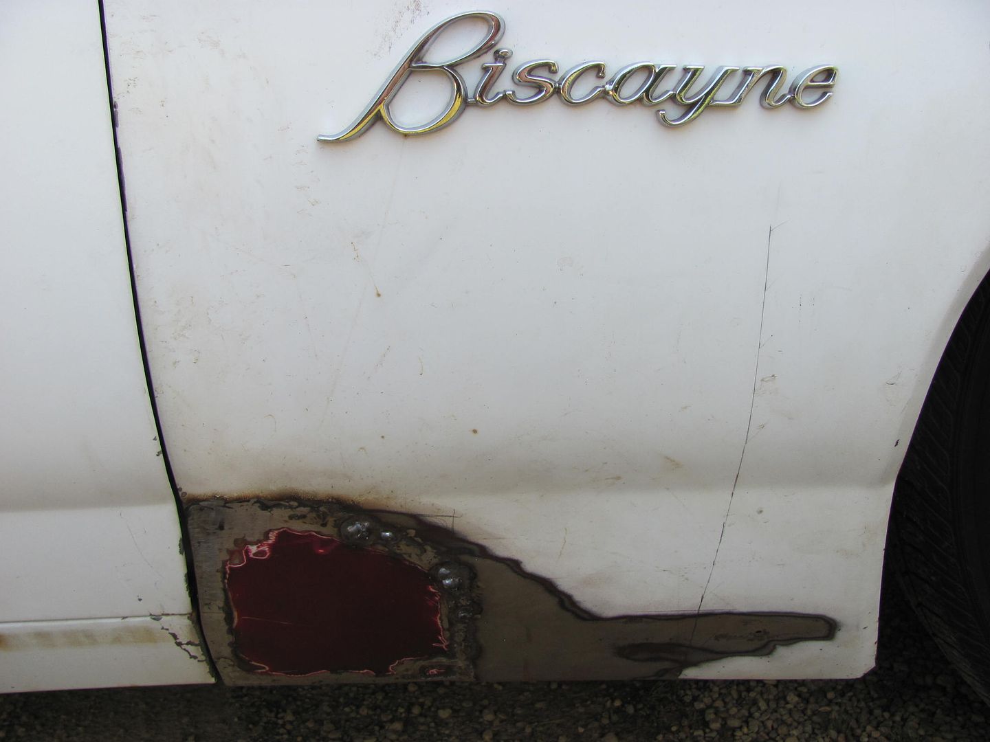 Where he had done a nice job of trimming his replacement prior to welding (especially for a first timer): 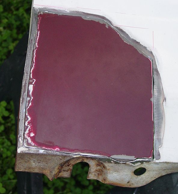 ..........I think a lot of the problems he experienced was due to not testing the welder set up on some scrap pieces first and additionally some weld contamination from residual rust scale. In trimming out repair panels for fenders, I have always tried to install a new flanged rear edge in order to minimize the vertical welds. The more welds, the more shrinkage, the more possibility of the panel moving. Where we could planish out the welds in an attempt to counter some of this shrinking effect, that is not possible behind the fender brace, so what he ended up with was this: 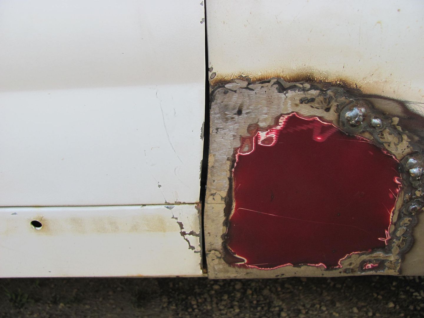 ......where you can see the replacement patch has pulled in a couple different areas to noticeably widen and distort the door to fender gap. I point these out not to pick on his work, but to highlight the possible effects of installing the patch in this manner that perhaps another method should be considered. Where the vertical weld seam on the right side was clear of the brace to allow for planishing the welds, this had not been done and serves as a good demonstration as to how the metal will shrink. If we were to look at the profile of the lower fender from the side, it appears much as an arc (to simplify things). Due to the heat from welding and the subsequent shrinking that occurs, the result in the case of an arc will be for it to lose some of its radius to more closely resemble a straight line. In this case, what we see is a valley down through the middle of the weld as the crown of the panel along the weld shrinks and forms more of a straight line. 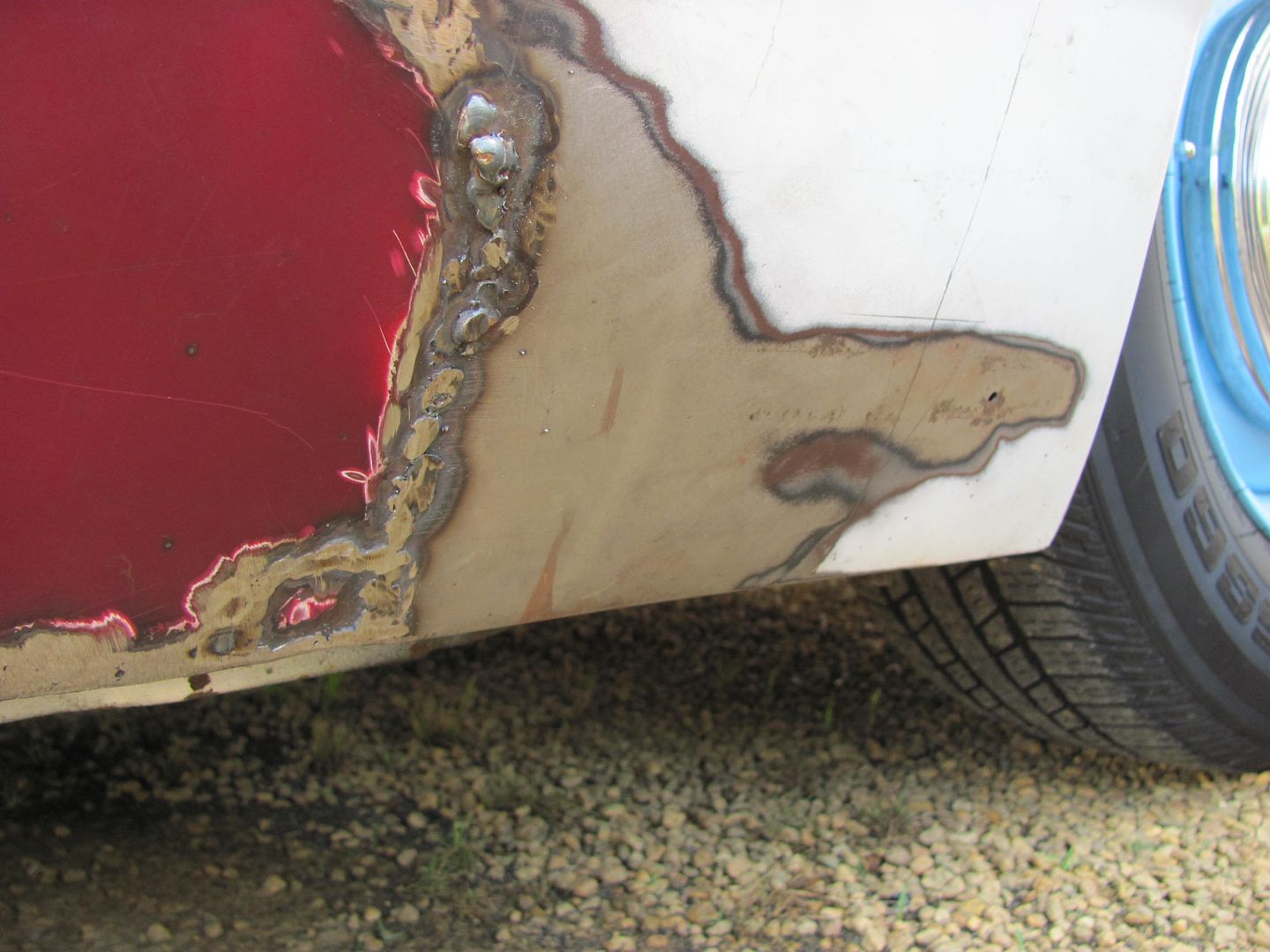 Prior to removing the fender, it was marked with a reference line to be able to duplicate the rear edge location once a new patch was fitted into place. Where the fenders rear edge had distorted, the mark was adjusted to provide for a consistent door gap. The fender was removed and Zach mastered fairly quickly the fine art of spot weld removal using a cutoff wheel. You can plainly see as the outer layer gets hot (speed is required here to generate heat), especially pronounced when the layer begins to thin, it will turn blue in color. When you begin to see the silver color of bare metal right next to the blue, you are now into the second layer. Time to stop there, grind a bit more around the perimeter of blue, and gently pry to check if the panel will release. 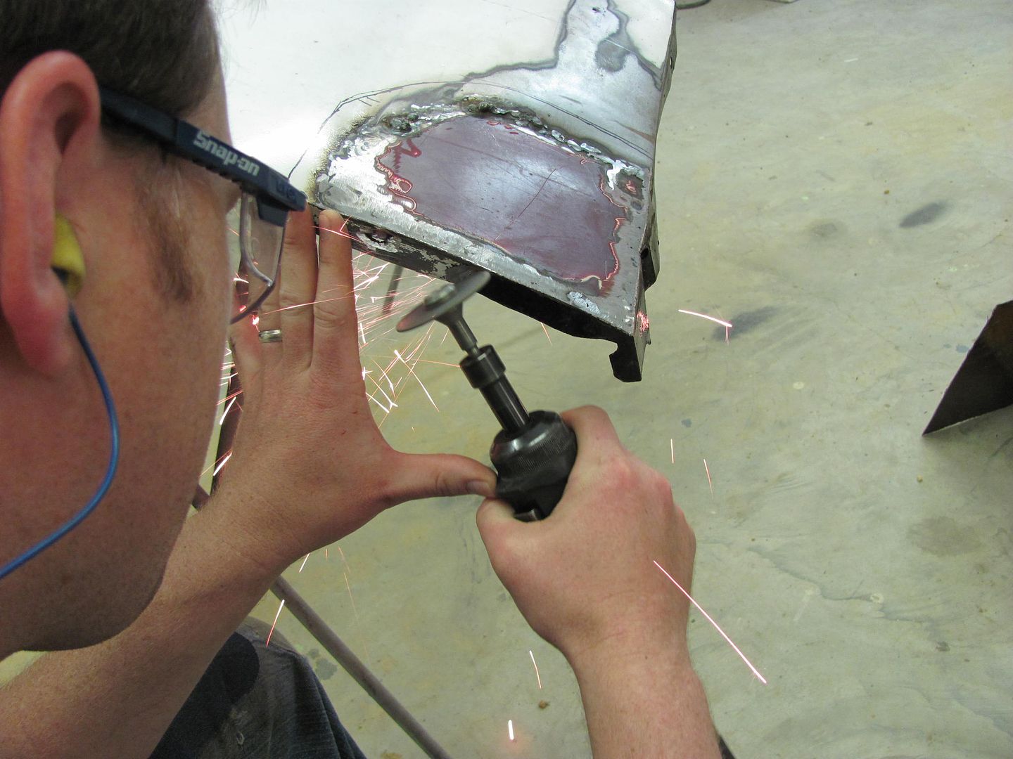 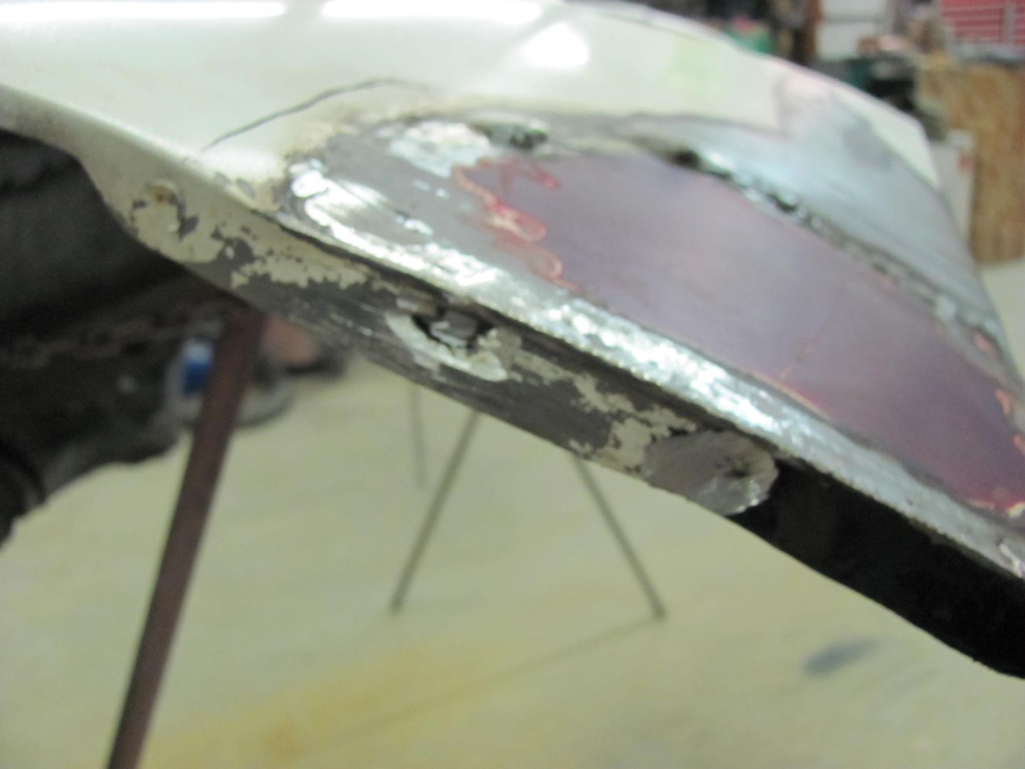 Where the lower flange of the fender had some rust issues of its own, we had to duplicate the contour around the lower mounting bolt. 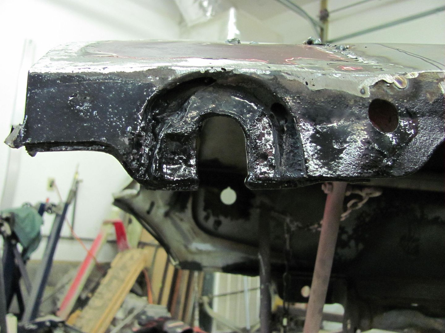 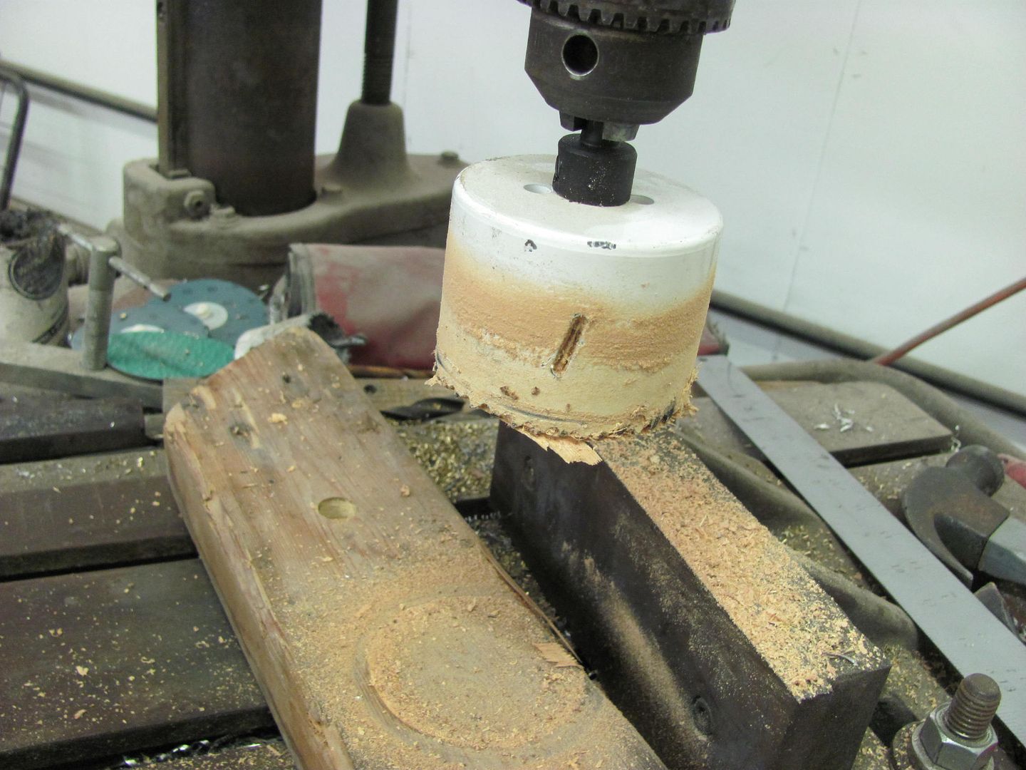 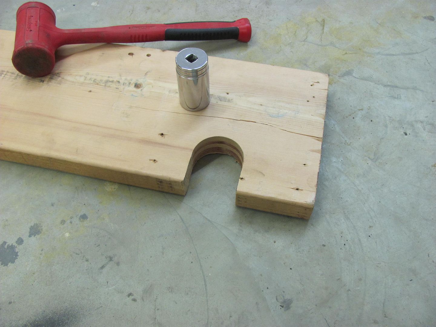 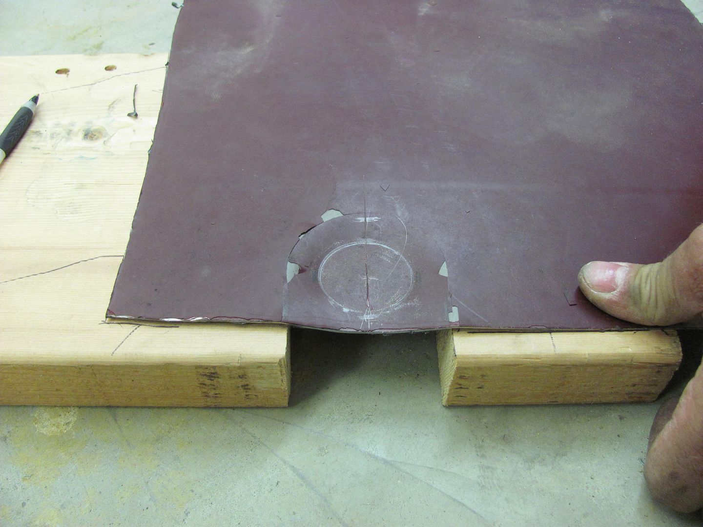 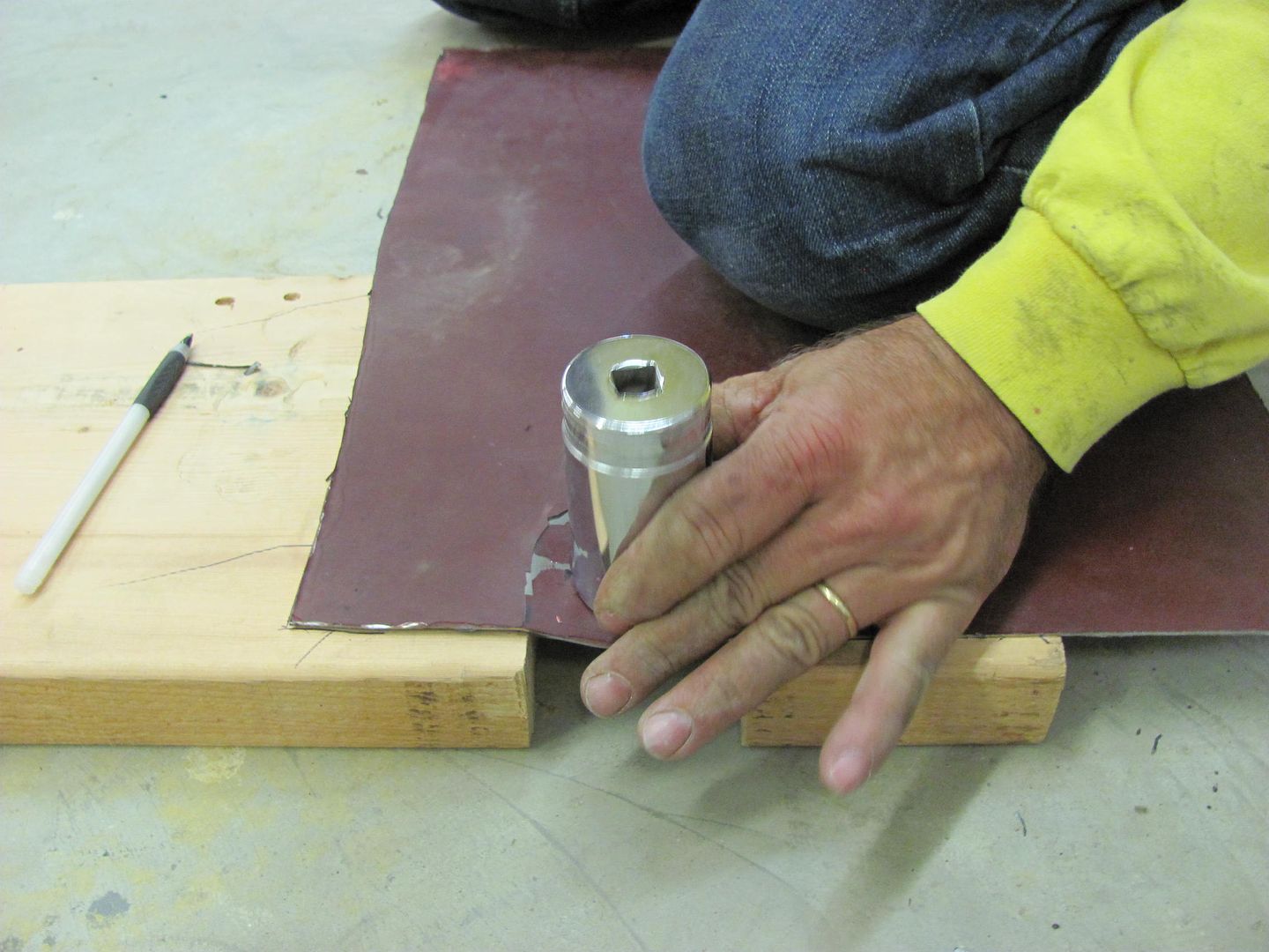 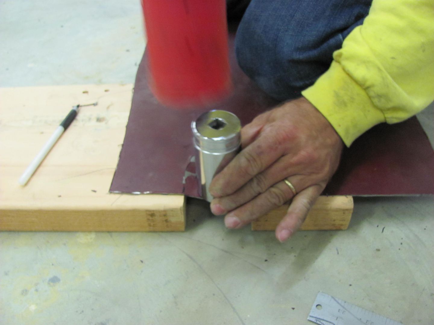 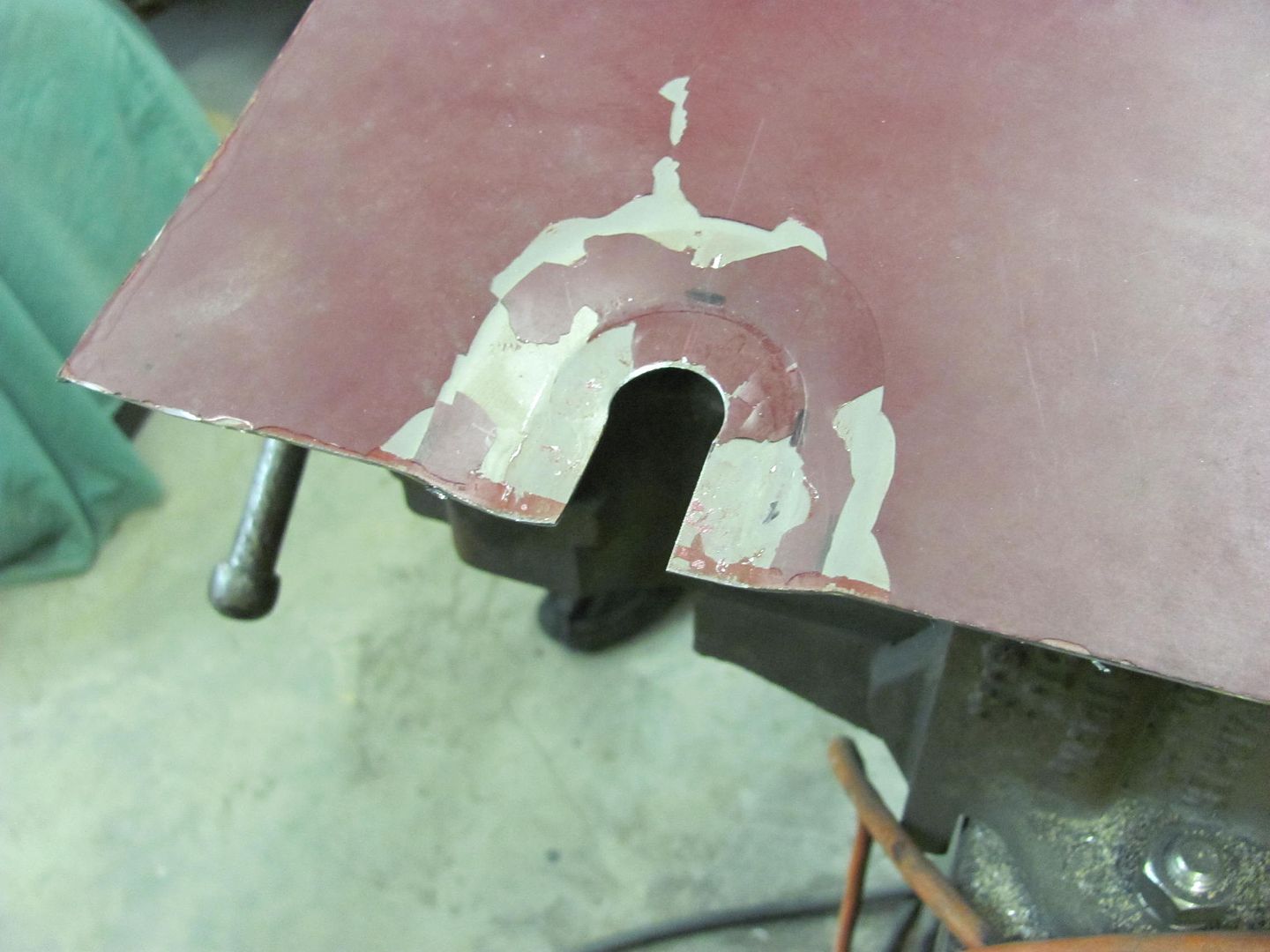 The lower flange was bent and the new weld seam was moved slightly to the right to remove some of the valley more easily and to also provide more room for planishing both the weld and the HAZ (heat affected zone) adjacent to it. 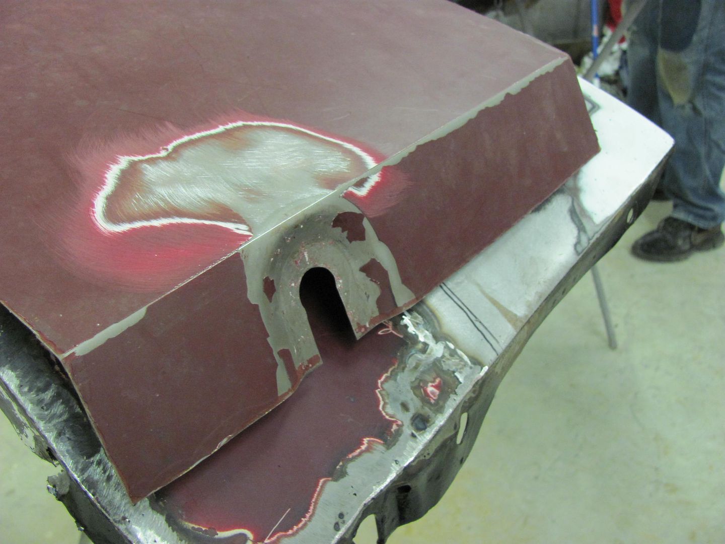 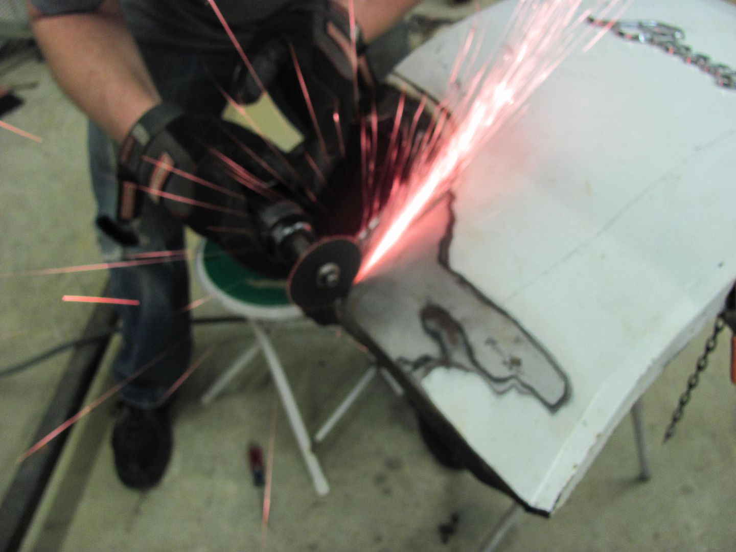 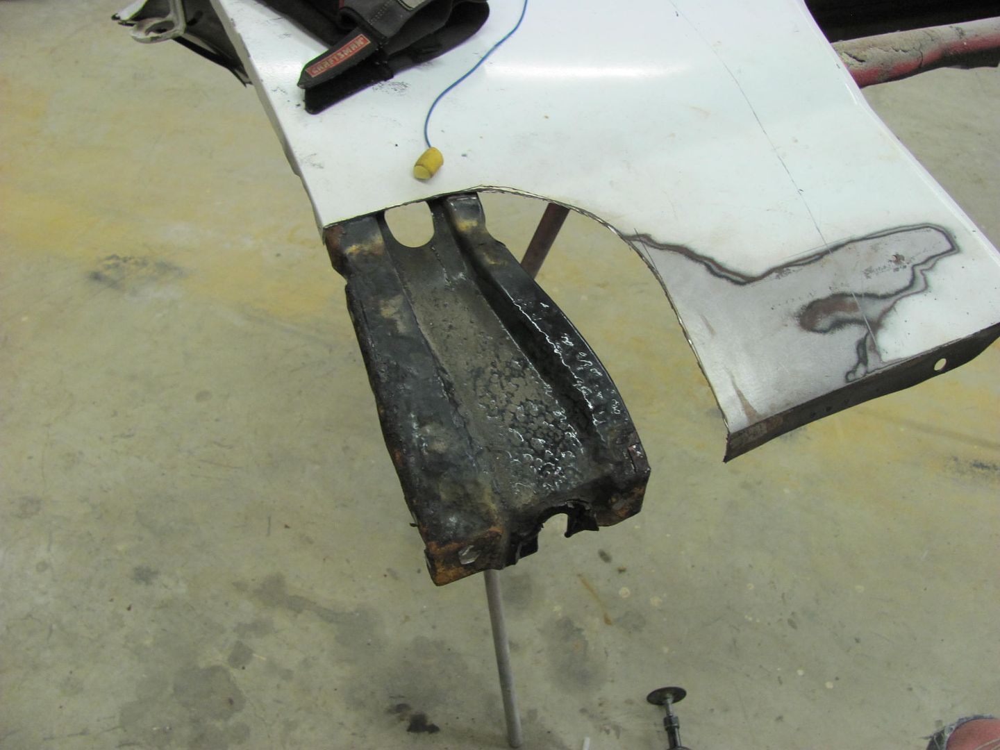 The fender was refitted (one of many times) to insure the distortion had been removed and we had a nice straight panel in alignment to the door... 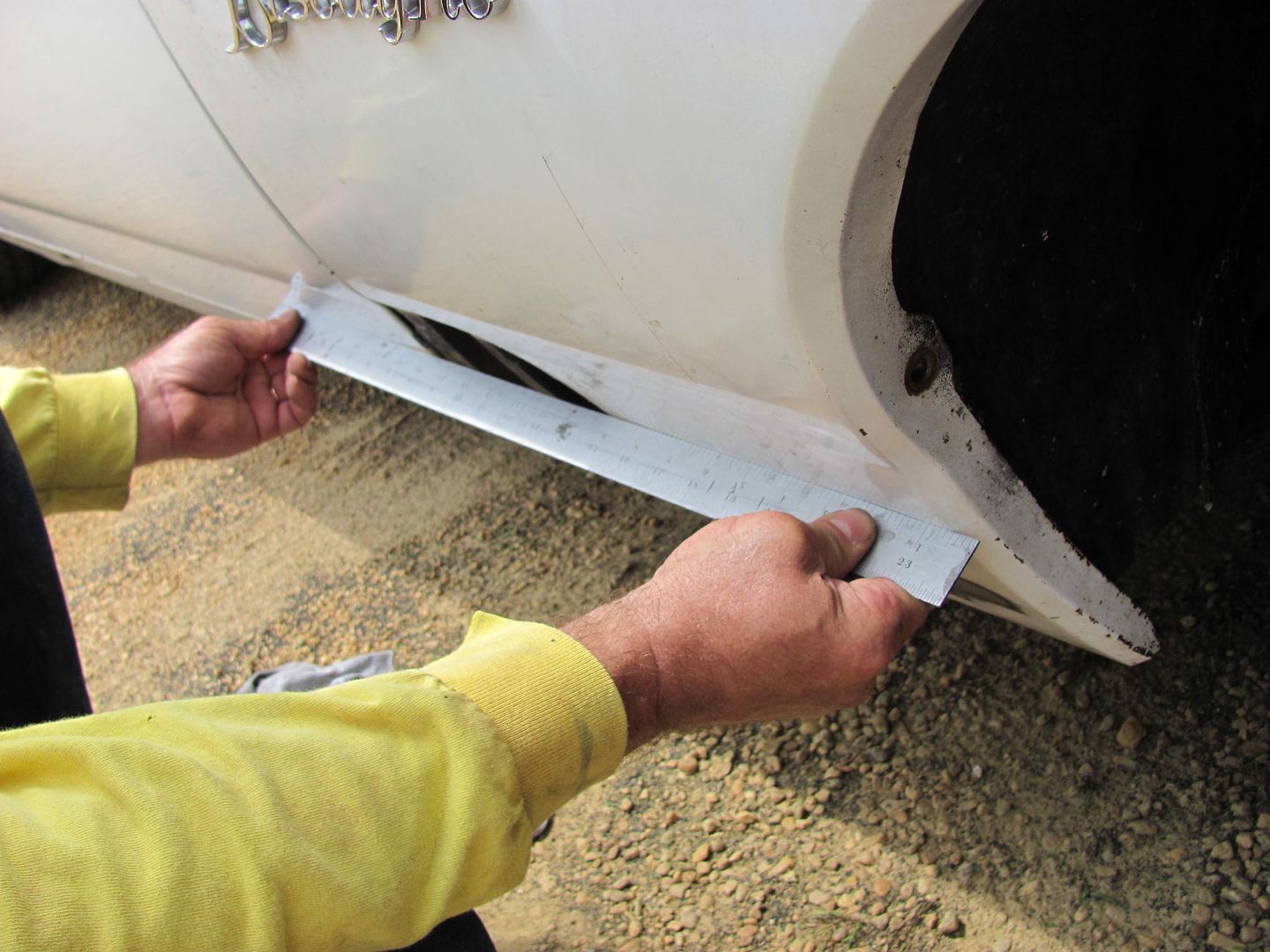 Then the patch was aligned to the lower flange mounting hole, trimmed to fit, clamped inplace, and marked for the fender rear edge flange. 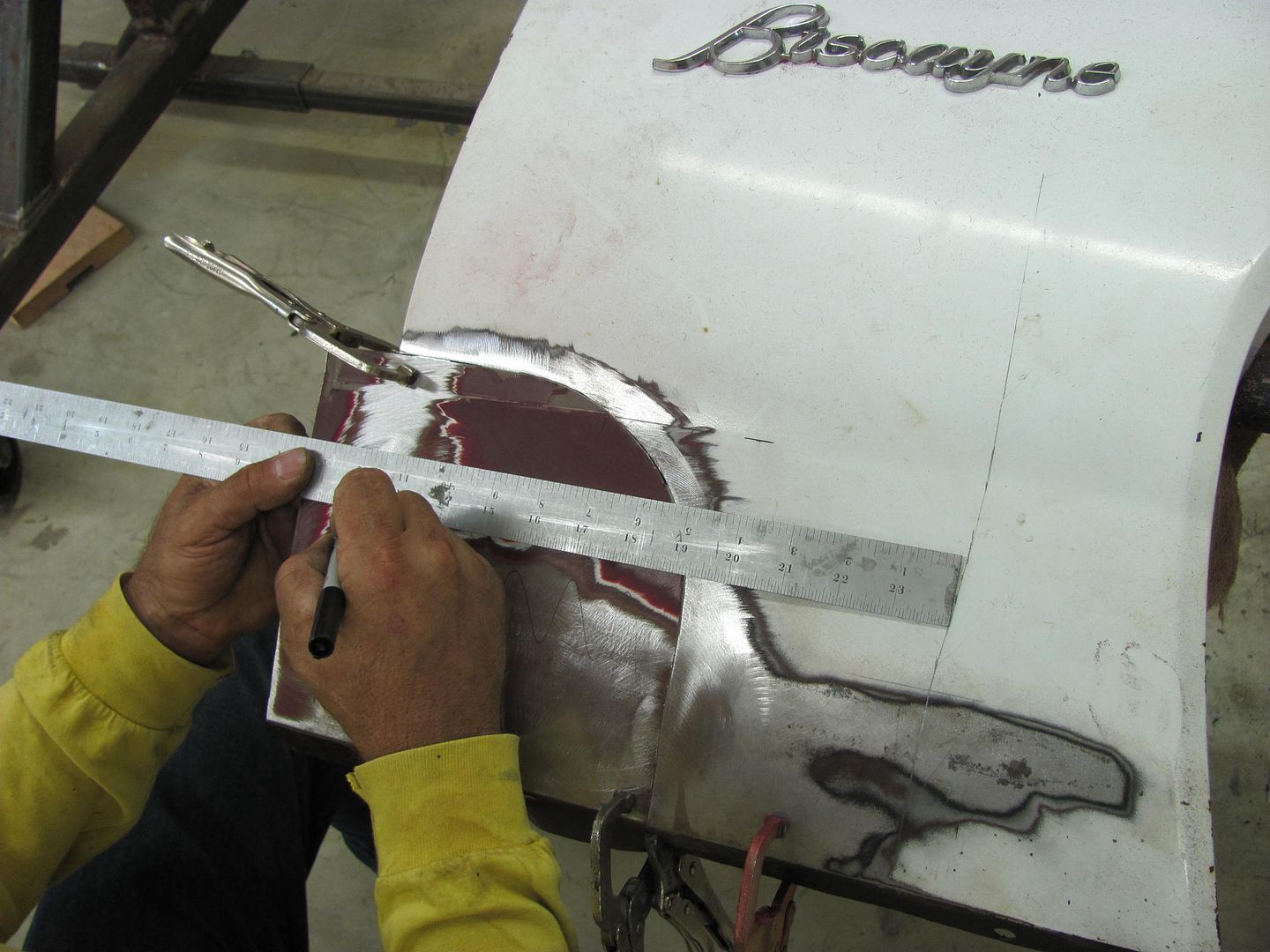 To show what is possible using "basic" tools, and since the bend is not prefectly straight, a short section of wedge "anvil" was clamped in the vice and a low crown hammer used to gradually form the bend. A shrinker and stretcher also came into play to duplicate the "arc" profile of the fender, and this was checked to the front edge fo the door.... 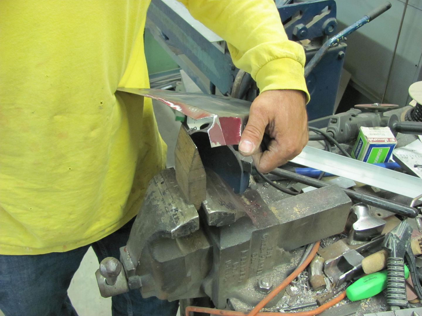 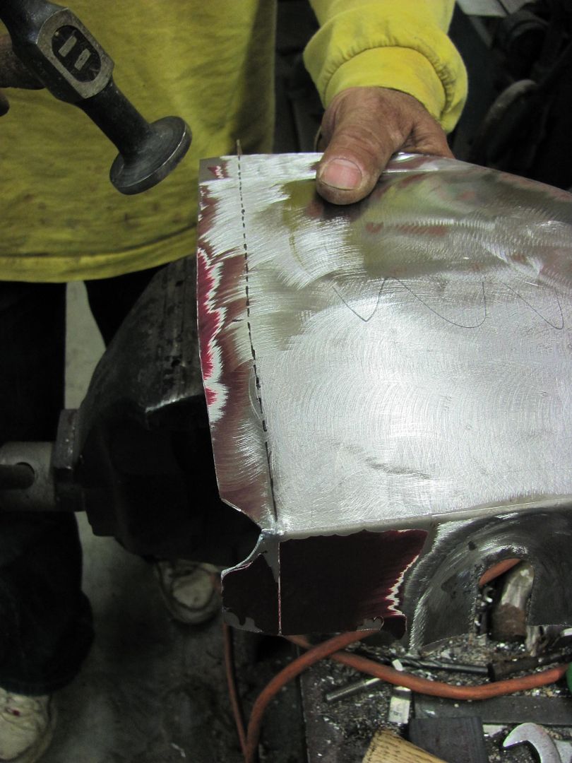 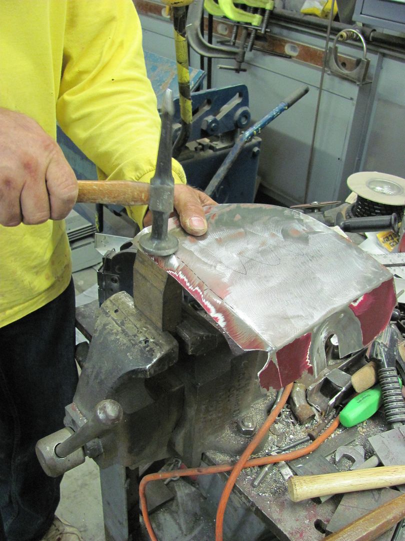 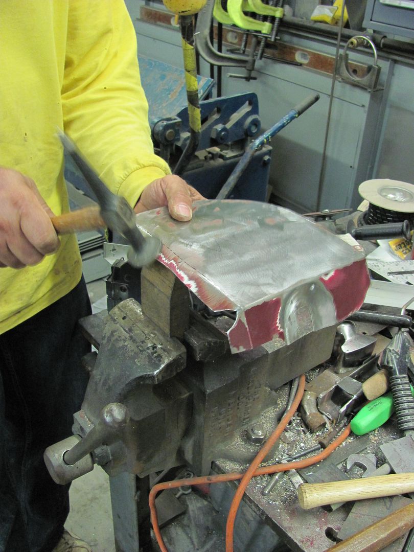 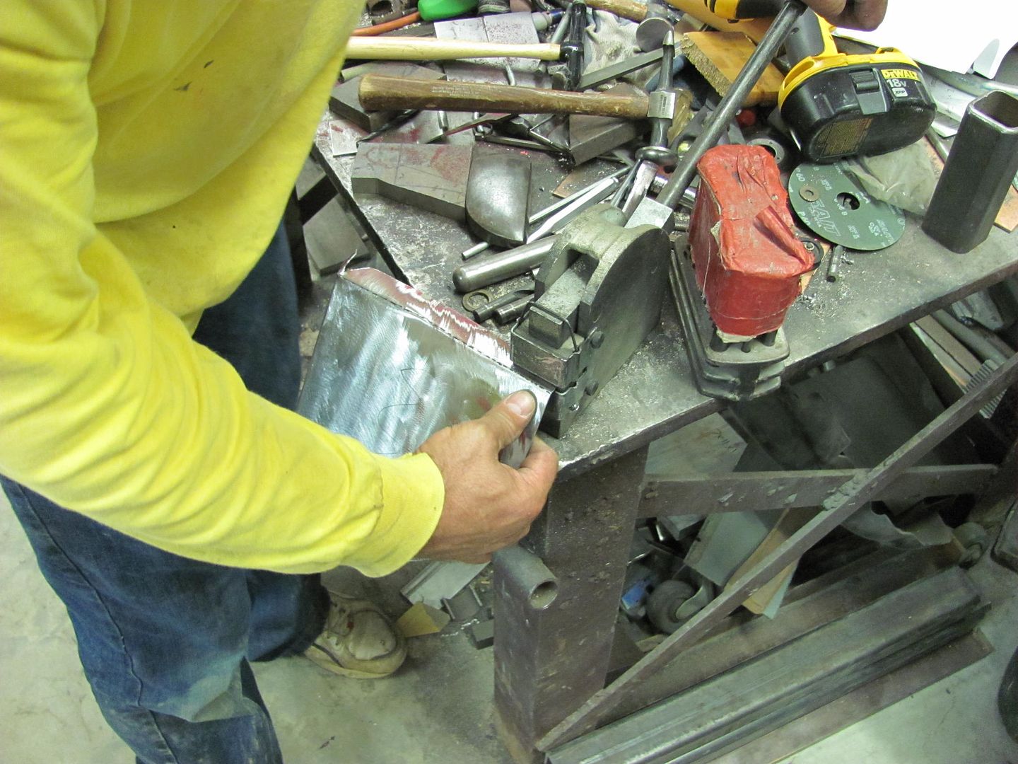 Then the patch was welded to the fender. I normally use weld "dots" in Mig welding sheet metal, and the machine gets set a little hotter (full penetration welds) and wire feed speed a little faster (less chance of blowout). Then the weld dots will be planished out, ground down just above flush (gets them out of the way for planishing the next set) and then planish the HAZ next to the welds as required. The top right cut was done using a large radius, which helps to reduce the shrinking effects that get comnpounded when working in a tight 90 degree corner. Where the inside radius will still shrink a bit more than the outside, the radius does make it a bit more manageable. Usually the HAZ on the inside radius is just planish a little more than the outside radius. 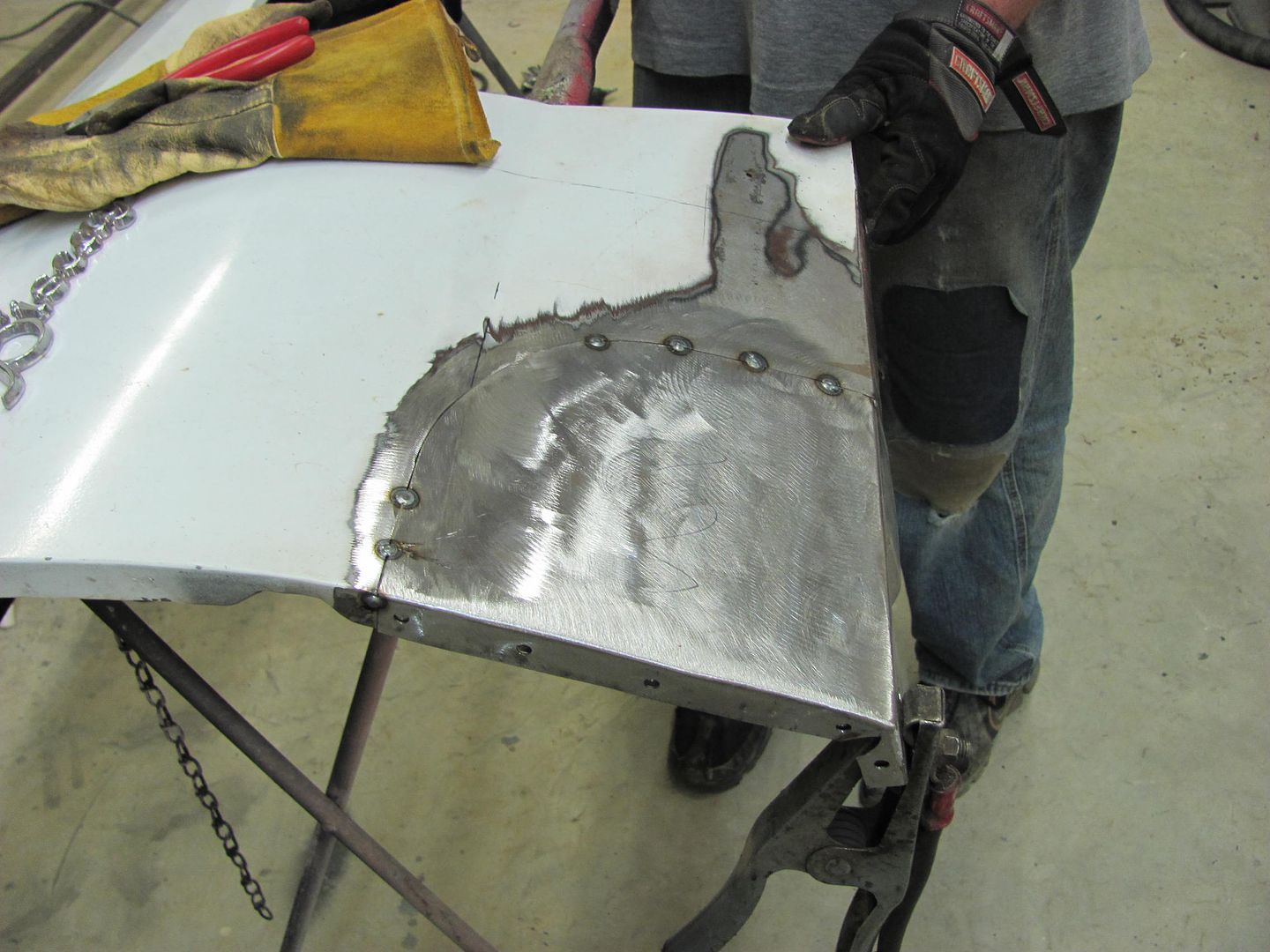 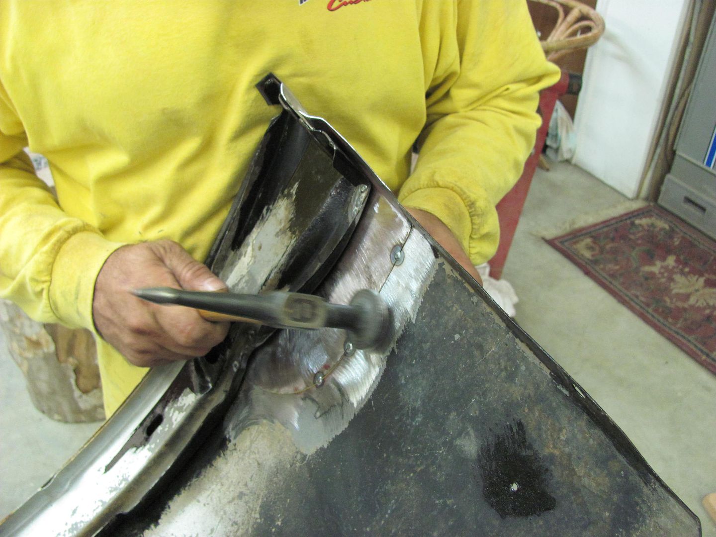 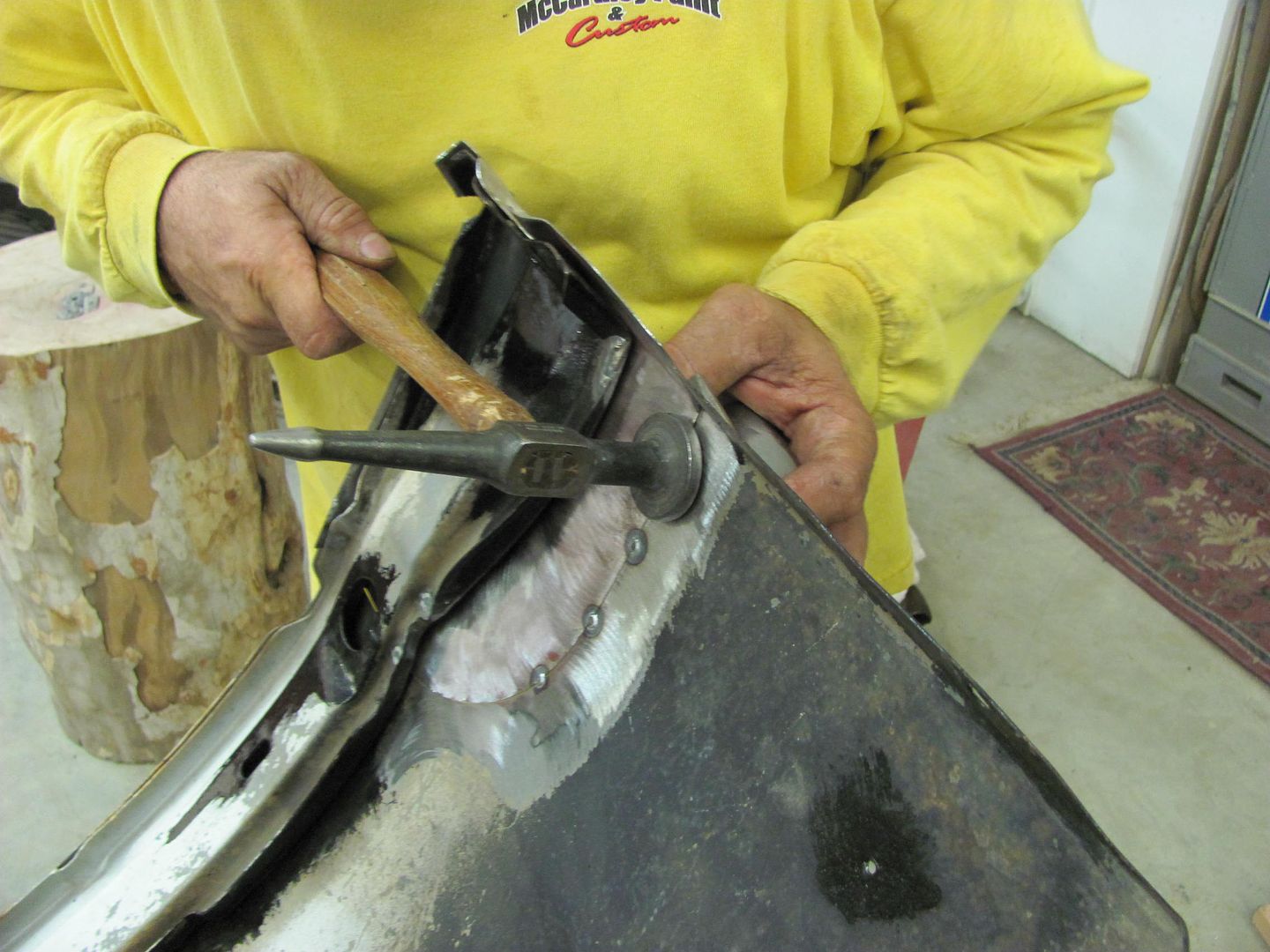 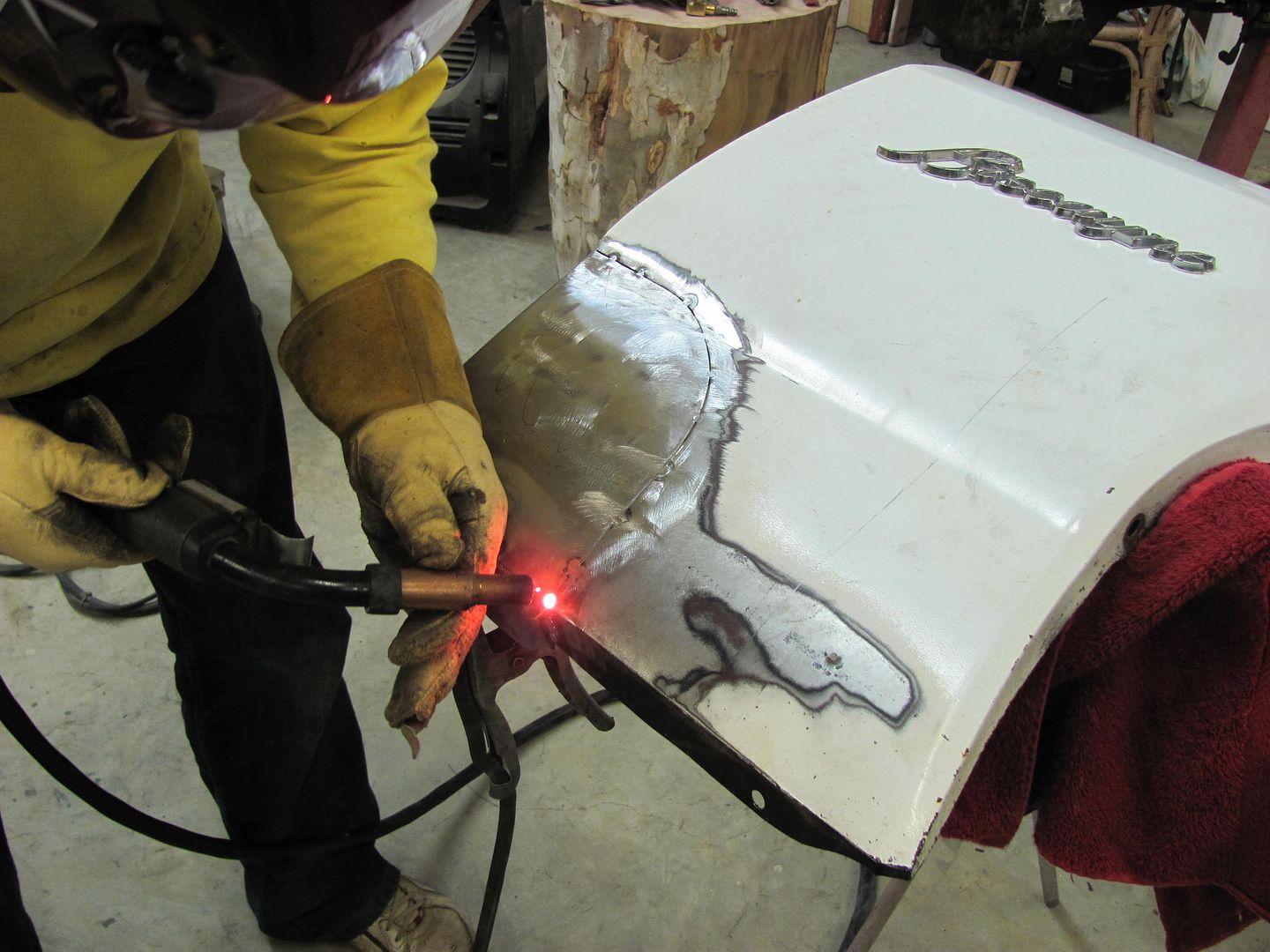 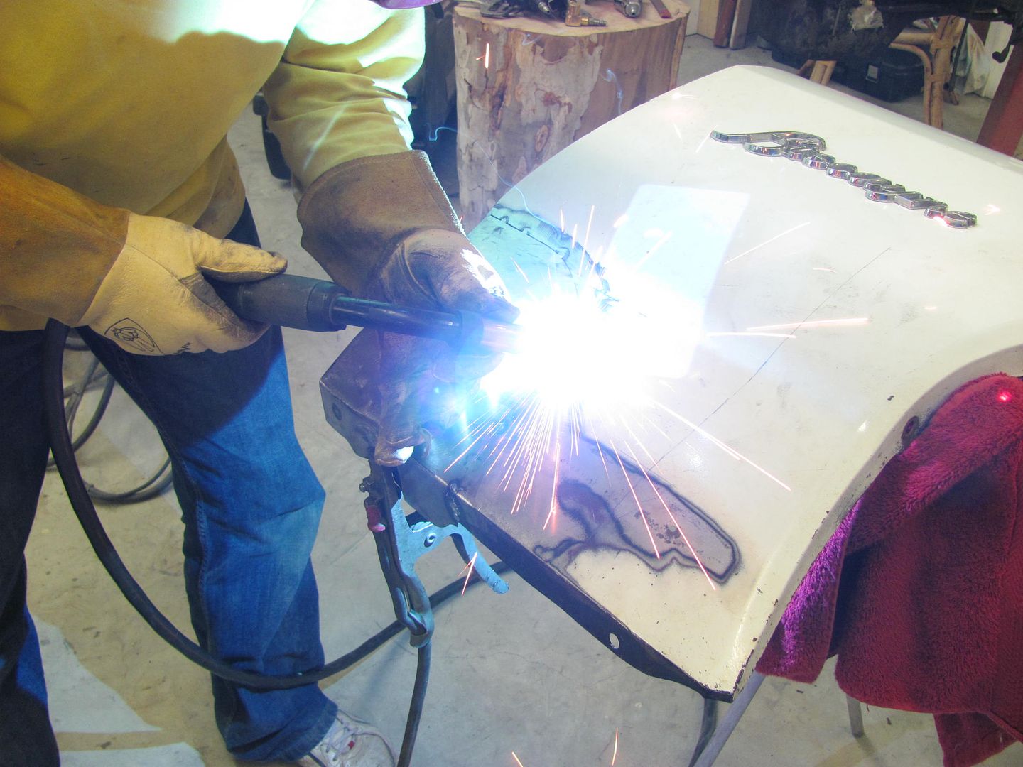 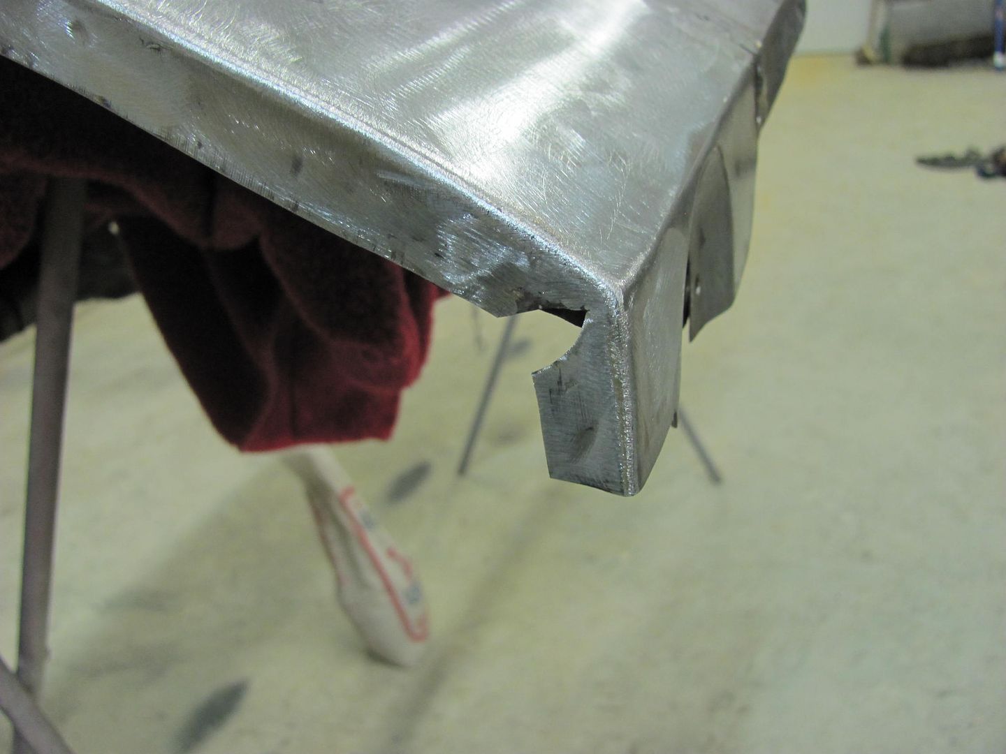 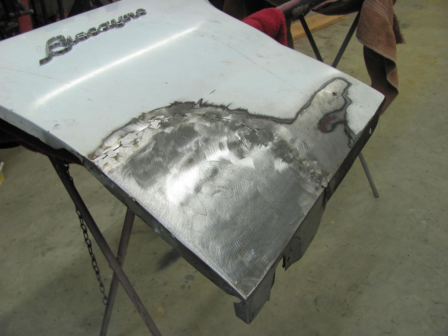 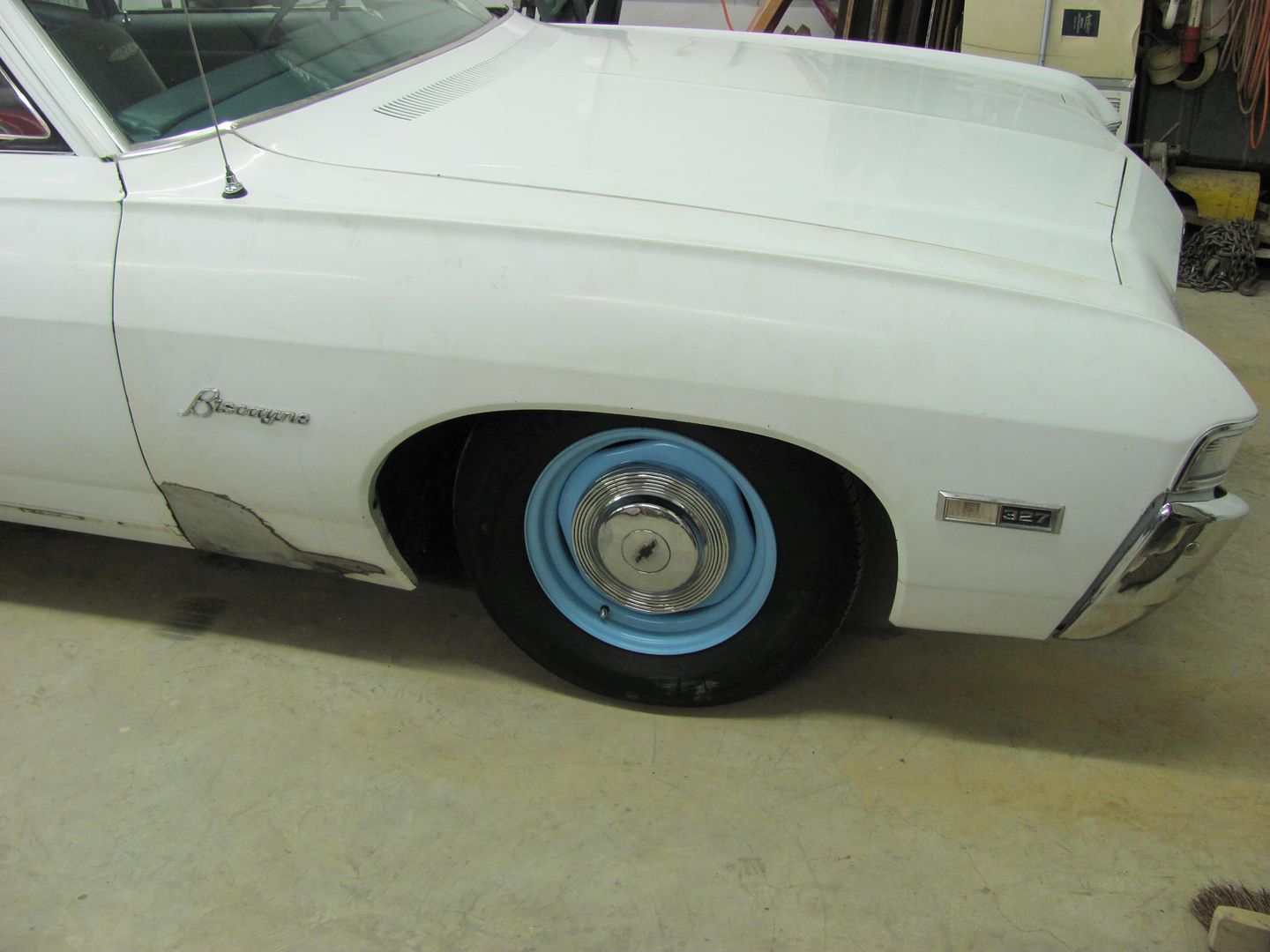 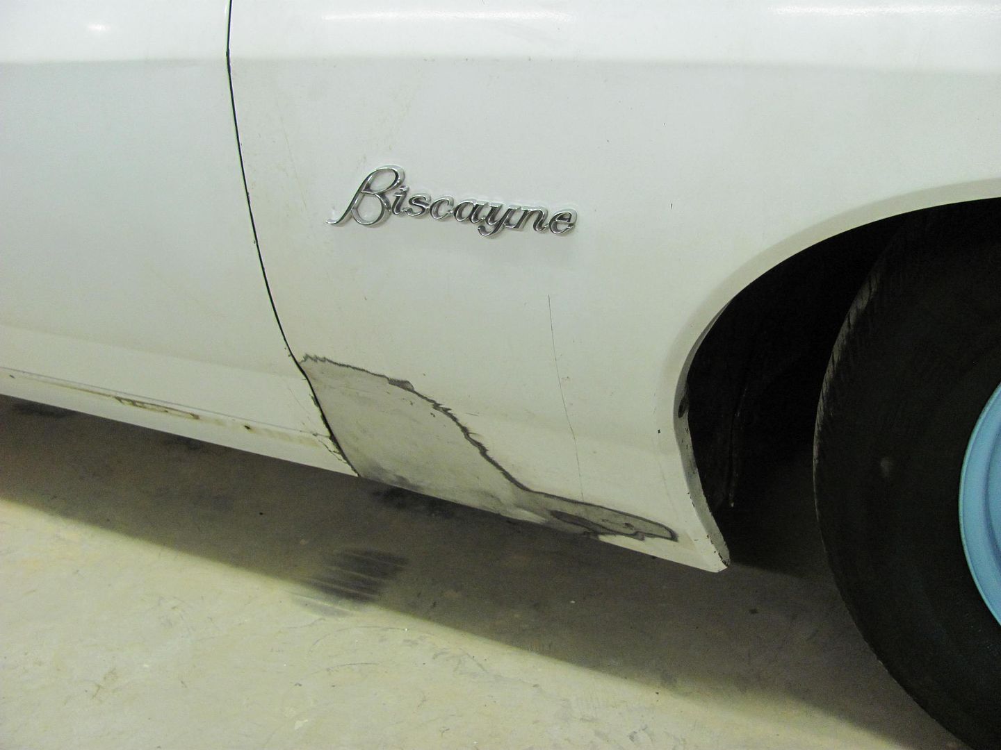 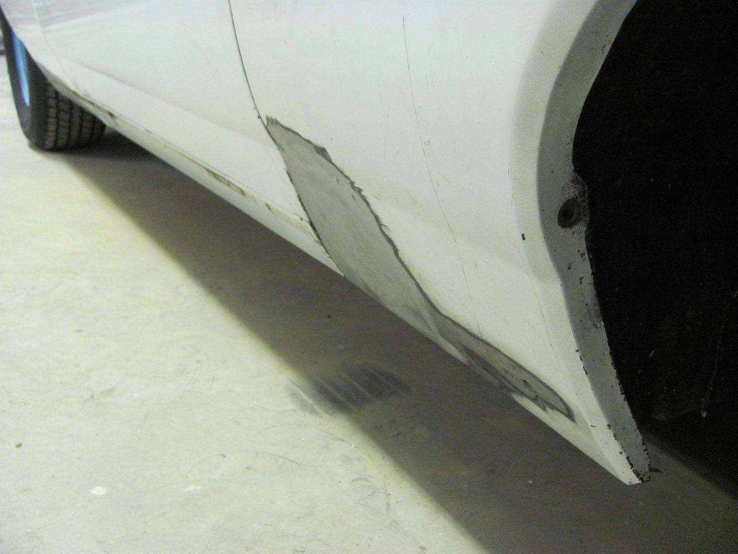 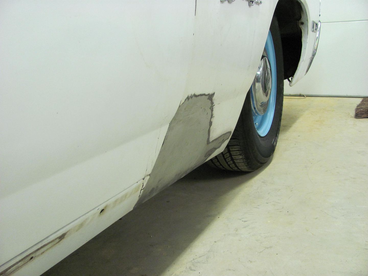 Where we did wind up with a slight depression right over the brace (should have put a bit more crown in the panel) Once Zach gets it all painted up it should last him quite a few years to come. I think he has a much better understanding and appreciation for working with sheet metal now, and look forward to his progress photos in the future..
__________________
Robert |

|

|
| Bookmarks |
|
|


 Threaded Mode