
|
Register or Log In To remove these advertisements. |
|
|
|
|||||||
 |
|
|
Thread Tools | Display Modes |
 07-18-2010, 01:41 PM
|
#1 |
|
Registered User
 Join Date: Mar 2005
Location: apple valley, ca
Posts: 2,670
|
My Air-Ride suspension fabrication pictures
This is the suspension portion of my build on the 47-59 section (Chevyrestoguy's '55 build).
I decided that I was finally going to bite the bullet and do an air-ride on my truck. I have been asking questions about air-ride for a long time. I do alot of my own fab work, but I needed some help on this one, so I enlisted the help of a buddy who owns a shop (Exile Fabrications, Apple Valley, CA, Mike Jones (owner) that specializes in this type of work. I gave him a outline of what I wanted the truck to do and turned him loose. Here's a cut/paste from my build of what we've done so far: 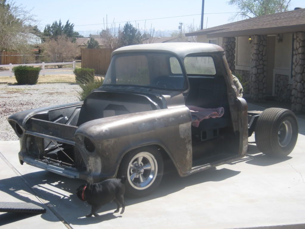 The plan was to remove the leafs in the rear and build a 3-link set-up with Slam Specialties RE-8 bags. Single 10 gallon air tank, 2 ViaAir 480 pumps, 8 valves. I want a slow-moving, quiet system. All the lines will be hard-lined. The front will get Slam Specialties RE-7 bags. It's not important for me to have the truck lay on the frame rails at full deflation. I just want to be able to raise the truck when I have to go over speedbumps, enter a driveway, or go down an uneven road. I've never had an airbagged vehicle, so this is new territory for me. While the truck is at Exile, we are going to engineer a way to make the Hydroboost work. With a Camaro subframe and with the master cylinder attached to the driver side frame rail, there isn't any room to route the exhaust. I'm running a 3" exhaust and there is NO room to route the pipes and still have the required air-space between it and the master cylinder. The plan is to move the pedal pivot tighter to the frame rail, scoot the Hydroboost and master cylinder aft, and run a pushrod and pivot assembly. I got the forward and aft leaf spring brackets cut off and removed the fuel tank. Also, the original leaf spring perches have been cut off. Mike temporarily tacked the housing to the frame to simulate the highest point that the housing can travel in the upward direction. He had to do this to determine the max length of the lower bars. The housing will never go this high when it's completed because the rockers will hit the ground before the rear end ever gets to this point. Plus, I plan to have a small snubber just in case. Don't know why I'm wanting to do that, but I don't feel comfortable with a metal housing and a metal frame rail possibly making contact without a least some small kind of a buffer between them. 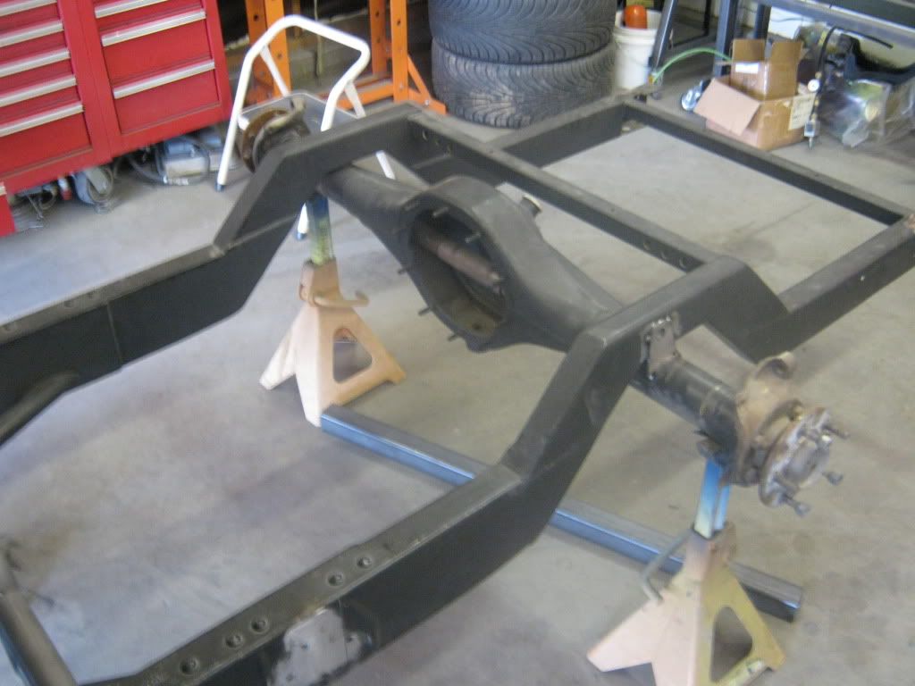 I took some pictures of the beast at the shop today. Mike is still hot and heavy on the dually because the owner added a bunch of extra stuff at the last minute. Here's a few shots of what he has done so far: 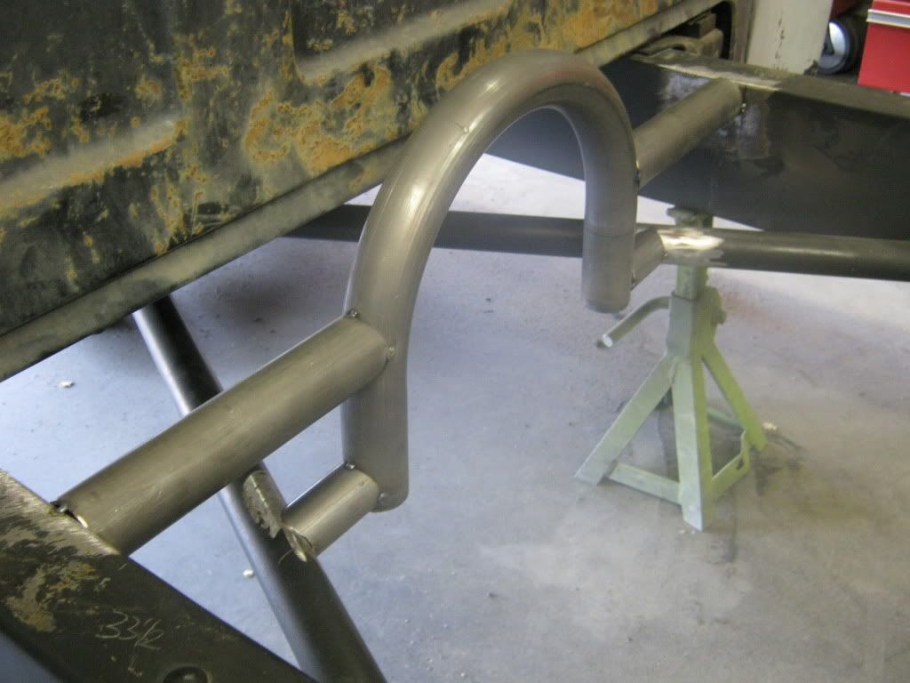 This is the beginning stages (just tacked welded in) of the support that will eventually have the forward attach points of the lower link bars and the upper bar. It is a 3-link set-up, so the upper bar will resemble a wishbone (2 attach points forward, 1 single attach point at the top side of the axle housing). He was able to attach the support to my X-member, so that'll tie everything together nicely. The frame is fully boxed with an x-member and all this extra tubing will ensure that my frame will NOT flex and should ride down the road nicely. 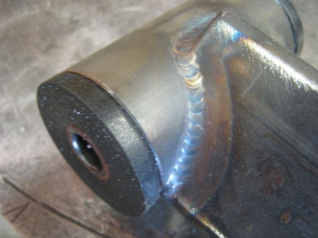 This is a shot of the one of the lower link bar ends. We decided to do a slightly different look and turn the 2"X2" lower tube on it's side and create a "diamond link". I thought I had a picture of the entire link but those are on my phone. Check out the welds. Nice, huh? I was hoping to get the new SS series bags for the front and rear, but when the order showed up, the fronts were the SS bags and the rears were the RE bags. No problem, either version is a great product, so once the parts finally arrived, some work got accomplished. Here's few pictures I took today. 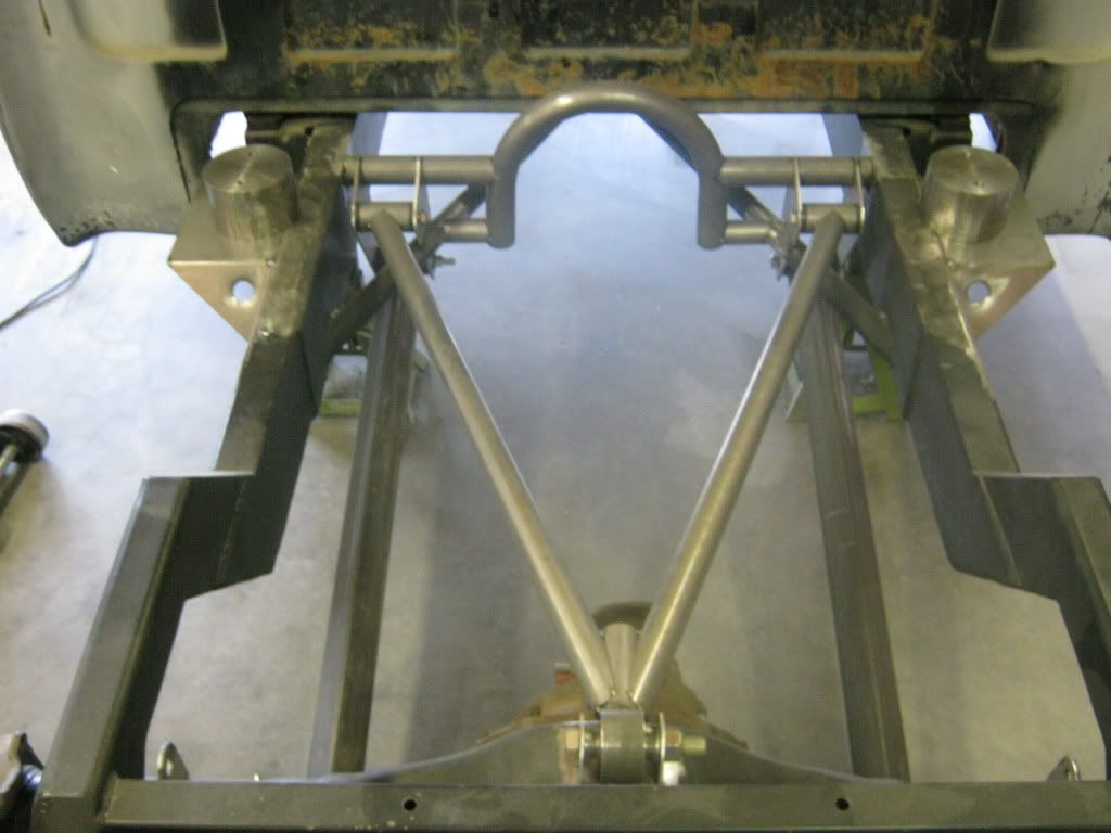 As you can see, everything so far is just tacked in place. The lower links and upper links are in and the system cycles really well. 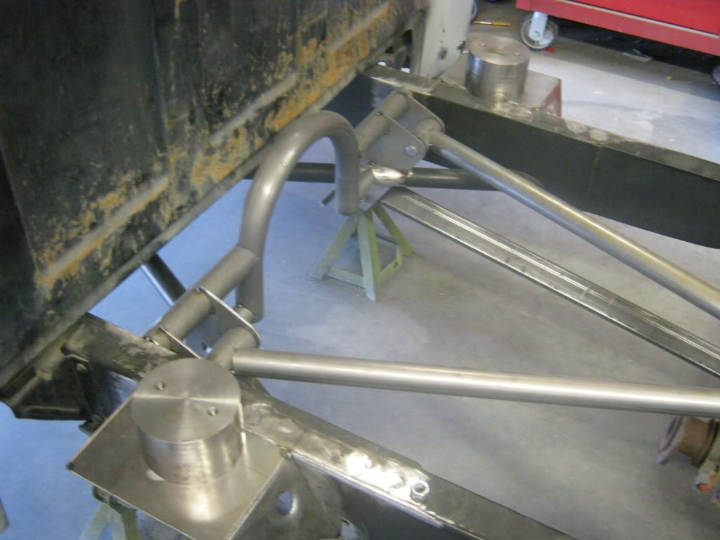 The forward brackets were a real challenge because of the existing x-member intersecting the attach points. Quite a bit of templates had to be made, but after some cutting and grinding, the brackets fit really well. They will be boxed and the flat areas will be dimple-died for a cool look. The bag mounts are tacked in, and the round piece of billet you see on top is a mock-up which simulates a deflated bag. That way, all of the measuring for any of the attach links is not based off of a floppy bag, but a solid piece. 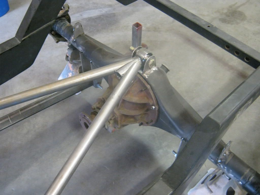 The upper bar is still missing some gusseting, and the attach bracket will be boxed and plated for strength. All of the attach points you see in the pictures will be done that way. We decided to use a Uni-Ball instead of a heim at the attach point on the housing because it'll work great for articulation. There's still a ton of work to do, but these pictures will give you an idea of what the system will look like. Once the bag mounts are finished and the bell-cranks get built, along with all of the dimple-died plates, it'll look sick. Mike had to finish a few projects ahead of mine before he could get going, so we're back on it. The guys at the shop that do the laser cutting messed up on some bracket patterns, so that slowed us up a bit. I made a few changes since the beginning, namely, more detail on the fabrication. I like the look of exposed, high quality TIG welds, and I like the look of lightening holes and feed-thrus. I want the design to meld with the functionality of the part. I don't like exposed things that look like an afterthought. Everything must flow, but still maintain it's functionality. In an earlier post, I mentioned that the rear suspension is going to have bell-crank arms because of the limited space due to the truck being a step-side and also the fact that it has a narrowed rear end. I want the bags to be as far outboard as possible for stability. Here are some pictures of the progress: 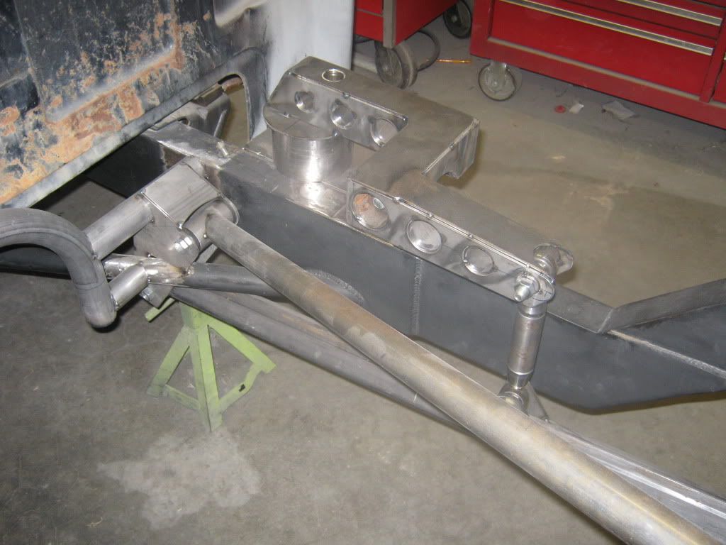 You can see the shape of the bell-crank in this shot. Currently, everything is tacked together until we get to a point where we're satisfied with the way it functions, then it will be final-welded. The link from the bell-crank to the lower trailing arm is chrome moly with welded-in rod end threaded bungs and the rod ends are the type they use on trophy trucks. They operate smoothly with no slop. The bolt for the pivot point is inside one of the lightening holes. There are still some gussets that will be added to the pivot point upright. The bushings at the pivot are the same as the ones from a trophy truck as well. The 6" round billet piece where the front of the bell-crank arm bolts to is an air-bag simulator, which simulates the air-bag at max deflation. Mike does not like using the bags during the fabrication stages because they can get damaged and they flex, which can be a problem if you're trying to get accurate measurements. 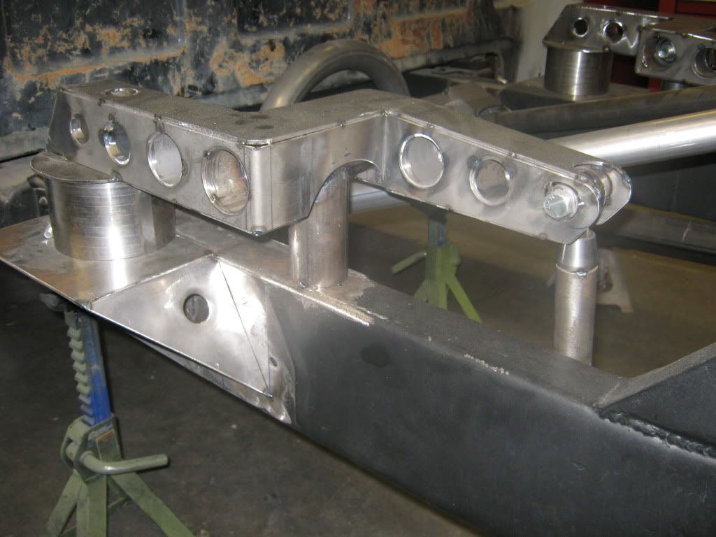 Close up shot of the arm. There will be gussets from the top of the framerail to the side of the pivot upright. Also, the relief cut-away will be opened up just a little more for additional clearance. We're still in the initial fabrication stage, so these things are normal and expected. 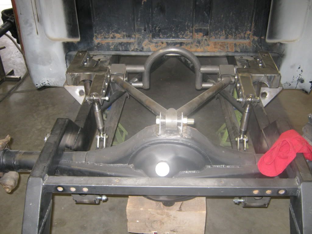 View from above. There's still alot of bridgework to do, shock mounts to make, figure out a swaybar set-up, and build the fuel tank, air tank mounts, compressor mounts, and battery box. The old shock crossmember will be cut out soon. It was staying in until the last because it was keeping the framerails parallel. I'm going to run out of room fast. We've got some ideas on packaging that will be very, very trick. Can't say right now, but the old saying about 10lbs of stuff in a 5 lb bag will be the idea. 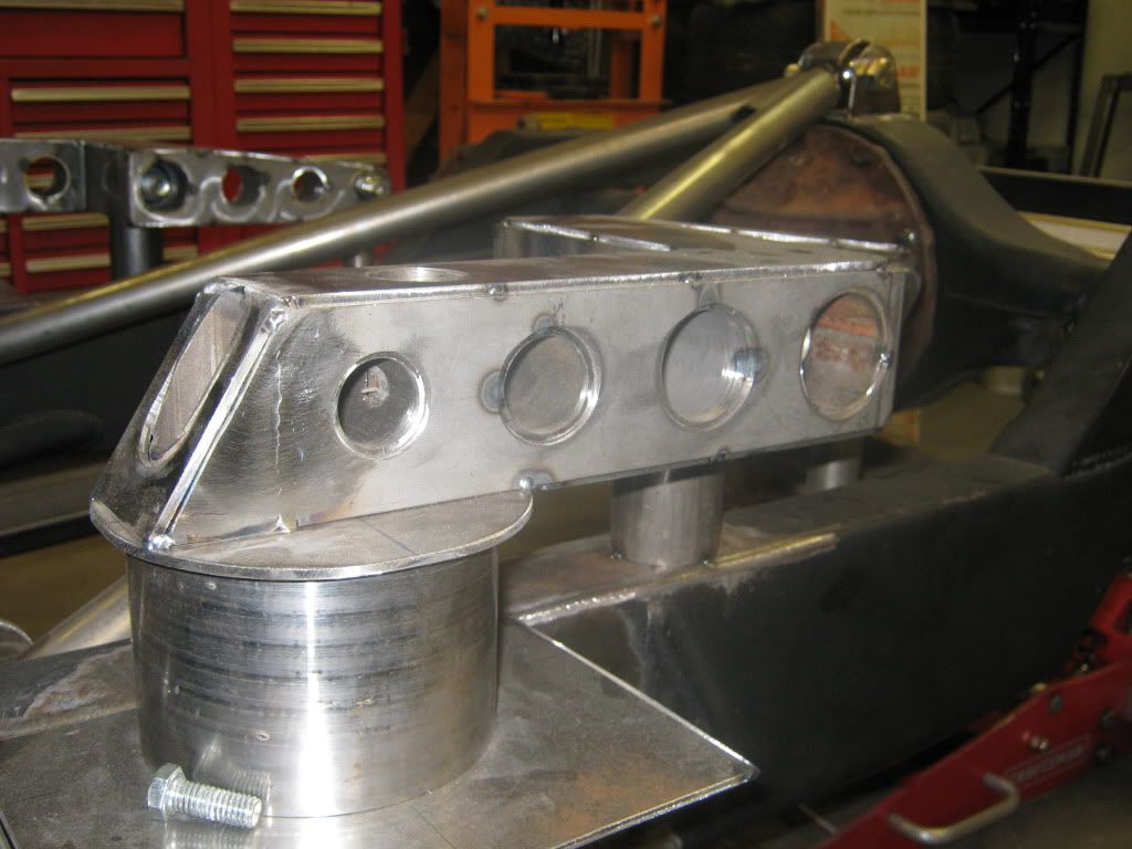 Another shot of the air-bag simulator I was talking about. Bag bolt access will be gained through the tubes that you can see on the top of the arm. The bell-crank arm pivot bolt will be accessed through the tube (4th one from the left) on the right. I'll keep posting when I get more pictures!!! |

|

|
|
07-18-2010, 06:05 PM
|
#2 |
|
Junior Member
Join Date: Jun 2006
Location: Frisco Tx
Posts: 311
|
Re: My Air-Ride suspension fabrication pictures
Looks real good man. Love the fab work involved.

|
|
|
|
|
07-18-2010, 06:39 PM
|
#3 |
|
low n' slo
Join Date: Mar 2009
Location: rosenberg, texas
Posts: 5,134
|
Re: My Air-Ride suspension fabrication pictures
looks great! i wish i could weld like that!
__________________
67 1/2 ton Suburban - Project DRGNWGN. Build thread  -_--_--_ _________ _--_-_ -/____|__|__\__ ,.,,,.,.,,.,|_O _______ O_] |
|
|
|
|
07-18-2010, 08:06 PM
|
#4 |
|
Registered User
Join Date: Aug 2004
Location: Folsom, Ca
Posts: 573
|
Re: My Air-Ride suspension fabrication pictures
great work man i like it! very very clean and to the point!
|
|
|
|
|
07-18-2010, 08:38 PM
|
#5 |
|
Registered User
Join Date: Jul 2005
Location: Riverside CA
Posts: 860
|
Re: My Air-Ride suspension fabrication pictures
I talked to Mike about doing some work for me.
He is a bad ass fabricator. |
|
|
|
|
07-18-2010, 08:42 PM
|
#6 |
|
Insert Title Here
Join Date: Feb 2006
Location: Dyer, Indiana
Posts: 5,679
|
Re: My Air-Ride suspension fabrication pictures
coming along great
__________________
BOBBY _69 SWB_ 1000 pics of 67-72's>> http://s193.photobucket.com/albums/z...-72/?start=all << |
|
|
|
|
07-18-2010, 09:32 PM
|
#7 |
|
Registered User
Join Date: Aug 2009
Location: Austin, Tx
Posts: 516
|
Re: My Air-Ride suspension fabrication pictures
Nice fab work. That's gonna be a sweet ride!
|
|
|
|
|
07-19-2010, 12:24 AM
|
#8 |
|
Registered User
Join Date: Oct 2008
Location: oxnard ca
Posts: 2,201
|
Re: My Air-Ride suspension fabrication pictures
|
|
|
|
|
07-19-2010, 12:40 AM
|
#9 |
|
New Member
Join Date: Sep 2006
Location: texas
Posts: 118
|
Re: My Air-Ride suspension fabrication pictures
man im no fabricator but you are one hell of a fabricator,that looks great
|
|
|
|
|
08-01-2010, 01:51 PM
|
#10 |
|
Registered User
Join Date: Mar 2005
Location: apple valley, ca
Posts: 2,670
|
Re: My Air-Ride suspension fabrication pictures
I'm super-busy at work right now, so I haven't had any opportunities to go to the shop, but Mike has been busy building the bridge that will tie in the forward crossmember, mount the shocks, and secure the fuel cell. here's some progress pictures:
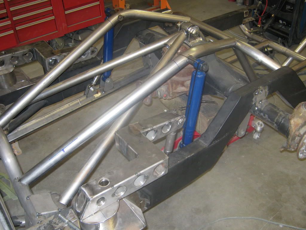 You can see the shock mounts in this shot. The suspension is currently set at the full-up position, so you can see that the shocks are compressed with zip-ties. You will also notice that the old shock crossmember has been removed, as has the old rear crossmember that supported the back of the old fuel tank. 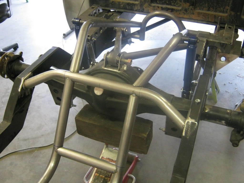 Rear corner shot looking forward 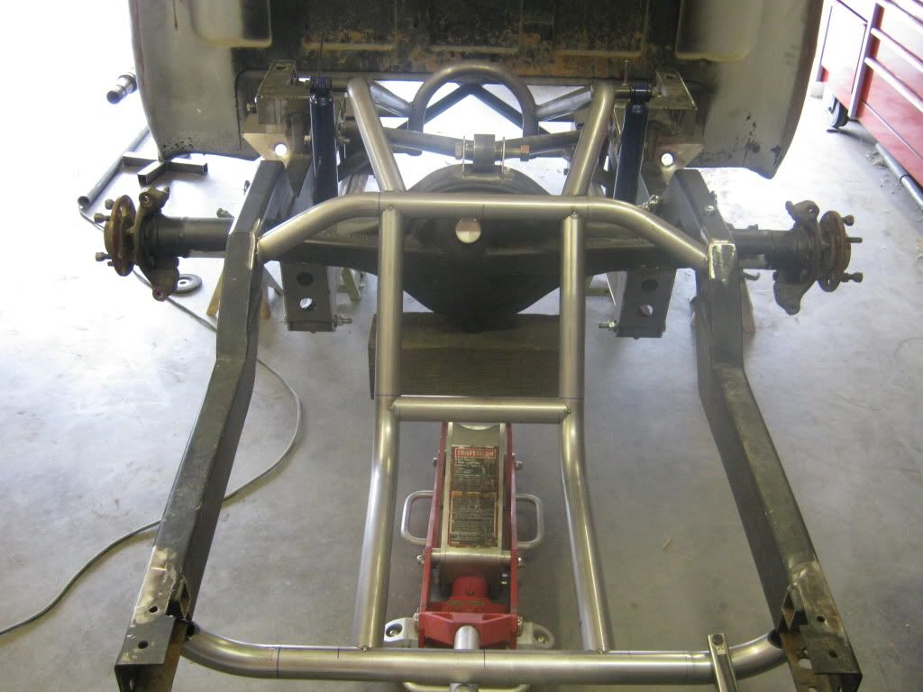 Rear shot looking forward. The tubes have a nice flowing shape, and in this shot you can see the fuel tank cradle. The square section of tubing just aft of the rear axle will house the battery. We've already designed up a cool battery box that will serve some other functions as well. 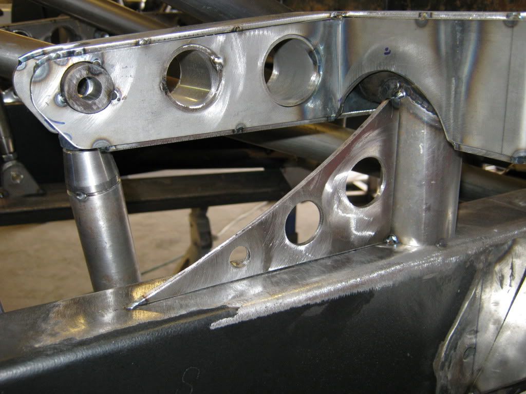 Here's a shot of the gusset I was telling you about in the earlier post. There will also be a triangular gusset on the forward side as well. It will be smaller to allow the cantilever arm to articulate forward without any interference. The aft side of the arm was also cut away a little more than before to allow sufficient clearance for the arm to travel fully. The plan is to finish plating and boxing, and do the final welding on Friday. Also, the upper wishbone is going to have some sheetmetal work done at the attach point by the rear axle housing in the next day or two. That will clean up the intersection where the tubes and Uni-Ball meet. You'll like those pictures because Mike's Tig welds are insane.... |
|
|
|
|
08-01-2010, 02:35 PM
|
#11 |
|
Chevy Only Tx
Join Date: May 2009
Location: Pecos,Tx
Posts: 1,061
|
Re: My Air-Ride suspension fabrication pictures
Awesome work
__________________
Chevy Only Tx......... |
|
|
|
|
08-02-2010, 11:10 AM
|
#12 |
|
Registered User
Join Date: Jan 2010
Location: Randleman, NC
Posts: 785
|
Re: My Air-Ride suspension fabrication pictures
Nice work!
|
|
|
|
|
08-02-2010, 11:11 AM
|
#13 |
|
67cheby
 Join Date: Sep 2008
Location: siloam springs ar 72761
Posts: 17,890
|
Re: My Air-Ride suspension fabrication pictures
Wow
|
|
|
|
|
08-02-2010, 12:39 PM
|
#14 |
|
Registered User
Join Date: May 2005
Location: Washington
Posts: 848
|
Re: My Air-Ride suspension fabrication pictures
Very nice work, keep the updates coming!
__________________
[PROJECT] FnLow69- 69 C-10 Full frame & layin' doors [PROJECT] Laidout53 - 53' Dodge Pickup, Full Kustom Build [PROJECT] "Hot Rod" 1931 Model A Bonneville style "Dream as if you'll live forever, Live as if you'll die today" ~ James Dean |
|
|
|
|
08-02-2010, 04:23 PM
|
#15 |
|
Senior Member
 Join Date: Jul 2010
Location: Dandridge, Tn. USA
Posts: 2,226
|
Re: My Air-Ride suspension fabrication pictures
great work guys
|
|
|
|
|
08-04-2010, 09:47 AM
|
#16 |
|
Registered User
Join Date: Mar 2005
Location: apple valley, ca
Posts: 2,670
|
Re: My Air-Ride suspension fabrication pictures
I took yesterday off because we were having some work done on the house (complete septic system changeout........lovely), and after the work was complete, I ran over to the shop and saw that Mike had been a busy boy.
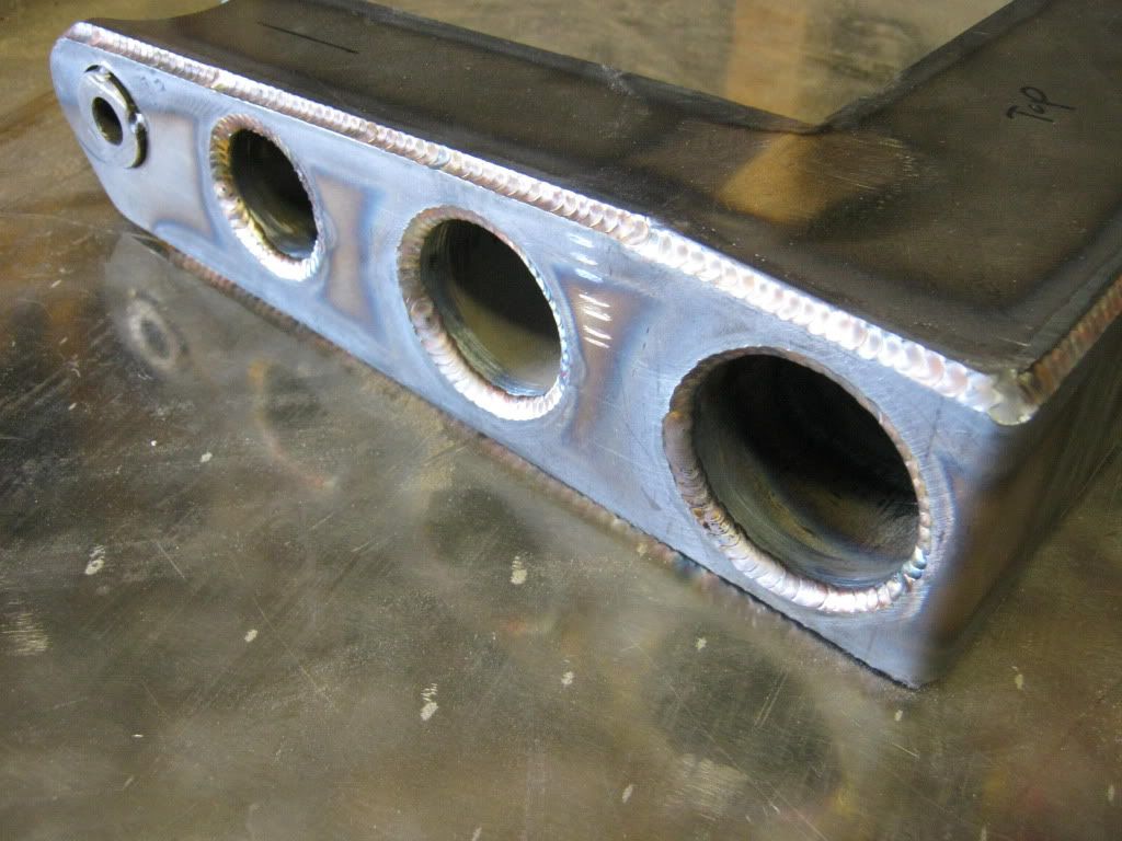 He was welding up all of the chassis, and I was able to grab this one and get some pictures of it while it was still hot. He did a LOT of welding on the cantilever arms. 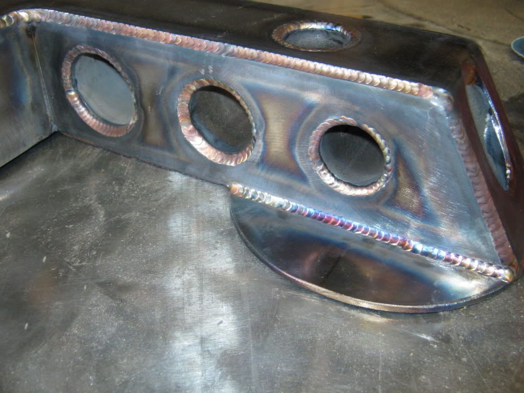 Another shot of the arms, with this one showing the airbag mount. 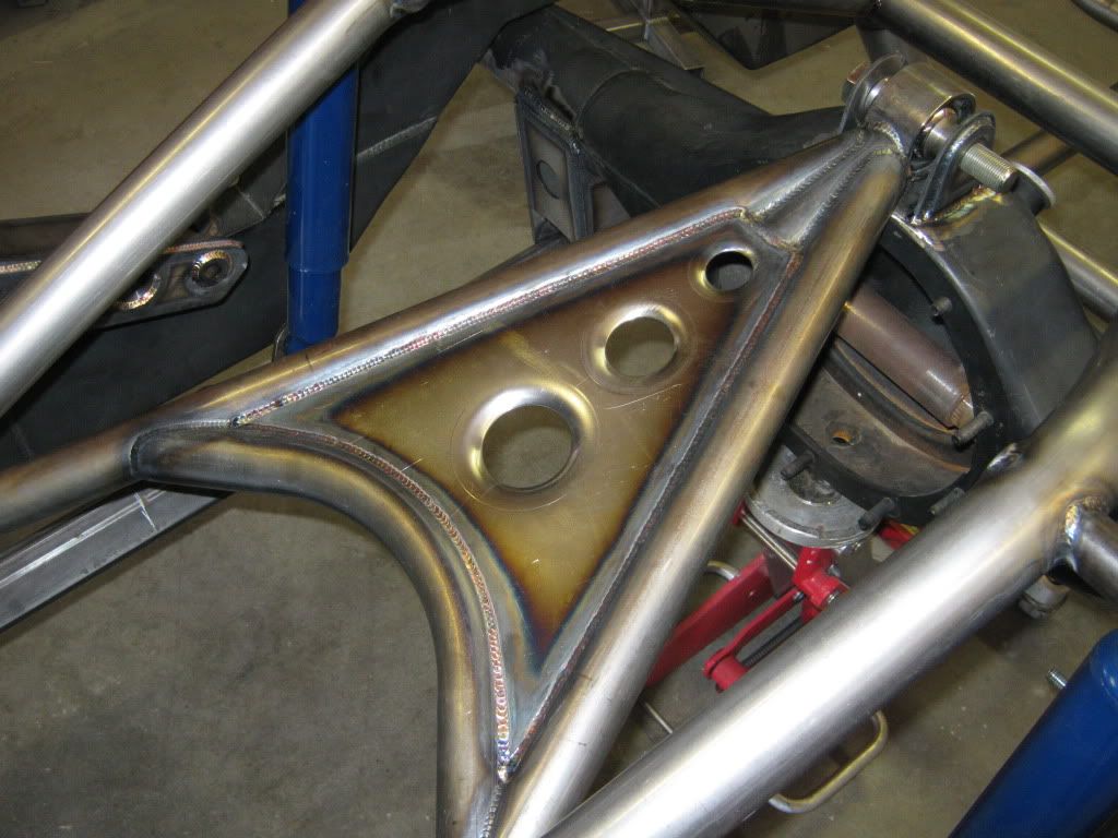 Here's the finished wishbone, with the dimple-died sheetmetal plate. It's .125 plate, fully welded. I wanted a curved front edge so it wouldn't look so triangular, and I think it turned out awesome. 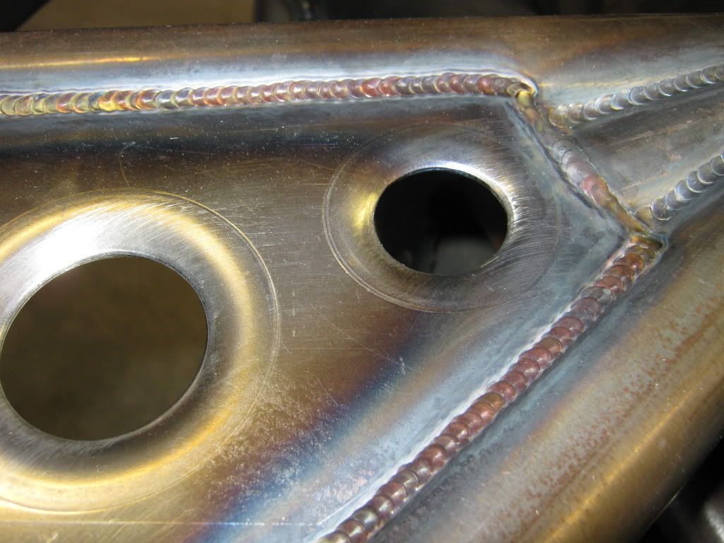 Close-up shot of the welds. That piece is now super-strong. My only concern right now is how I'm going to paint (or powdercoat) the chassis without burying all of those bad-ass welds.  Here's a shot showing the finished arm with an airbag (Slam RE-8) installed. The gusset and bag mount have also been welded fully. I ran it through full-up/full-down and it operates perfectly. No binding or squeaking, and zero slop. The next plan is to bolt everything up, run temporary air lines (I'm plumbing it with stainless hard-line later) and cycle the system. |
|
|
|
|
08-04-2010, 11:51 AM
|
#17 |
|
Registered User
Join Date: Nov 2007
Location: Phoenix,AZ
Posts: 107
|
Re: My Air-Ride suspension fabrication pictures
Amazing work! Nice job. Your truck is awesome.
|
|
|
|
|
08-04-2010, 05:37 PM
|
#18 |
|
Registered User
Join Date: Mar 2005
Location: apple valley, ca
Posts: 2,670
|
Re: My Air-Ride suspension fabrication pictures
Got to the shop early this morning and finished the temporary plumbing because it was killing me to see the truck on it's wheels and laid out.
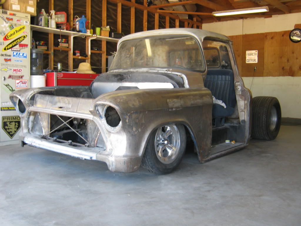 I love it. It has a rake to it when it's laid out, and that's exactly the effect I was hoping for. The next plan is to get it back home where I can do some more fab work. I really want to mount the bed and figure out new attach points because all of the original points have been covered up by all of the air-ride set-up. I've got some trick ideas for the bedfloor/tonneau. The days of this truck hauling anything in the bed are over. It'll go back to Mike's in a month or two to finish the gas tank, air tanks, compressor mounts, and some finish welding on the hydroboost system. |
|
|
|
|
08-04-2010, 09:08 PM
|
#19 |
|
chevy runs deep
Join Date: Mar 2006
Location: PHOENIX AZ
Posts: 1,074
|
Re: My Air-Ride suspension fabrication pictures
wow nice welds
__________________
RAIDER NATION 1969 c10 swb soon 2 b on the road... My LWB is a SWB now http://67-72chevytrucks.com/vboard/s...d.php?t=498241 |
|
|
|
|
| Bookmarks |
|
|


 Linear Mode

