
|
 04-30-2012, 03:20 PM
|
#1 |
|
Registered User
Join Date: Nov 2011
Location: Idaho
Posts: 857
|
Ls alt wiring
Currently installing an 06 ls in my 69 c/10 and was wondering were to hook up the brown wire on my truck That tells my gauge if the alternator is charging. The alt that came on my motor has two wires brown and gray then it has the large red wire that goes to bat+. I'm thinking brown to brown also does it need a resistor in between the connections just not real sure and dont want to burn up a good alt or the truck.
Posted via Mobile Device |

|

|
|
04-30-2012, 05:54 PM
|
#2 |
|
Truck and auto performance nut
Join Date: Feb 2007
Location: McKinney,Texas
Posts: 3,848
|
Re: Ls alt wiring
Just hooked up the 12v on the back of the alternator straight to the battery...left out the 2 wires for the connector...charged just fine as a 1 wire setup.
__________________
Kurt - '68 GMC short step - NIB '09 LY6 6.0L crate motor w/mods, NIB '12 crate 4L85e w/billet 3k stall Circle D, 3.73 posi 12 bolt, DynaTech f-swap headers, 3/4 drop, handling mods, etc. - my toy '72 Chevy LWB C-10 Highlander - 350/350 ps/pb/tilt/ac - not original but close '06 Chevy TrailBlazerSS - LS2/4L70e - little black hot rod SUV - my DD '18 Kia Sorento - wife's econo-driver '95 Chevy S10 - reg cab shortbed, LS, 4.3, auto... my '68's powertrain and chassis build -links broken A surprise phase - carb to efi -links broken |
|
|
|
|
04-30-2012, 06:36 PM
|
#3 |
|
Registered User
Join Date: Sep 2009
Location: ottawa,canada
Posts: 4,550
|
Re: Ls alt wiring
I just have the big red wire from starter to alt....and the pcm has a small red wire that plugs in the alt.....thats it...guage works, and seems to be charging...
__________________
my build threads '86 C10 http://67-72chevytrucks.com/vboard/s...d.php?t=415628 '67 C10 http://67-72chevytrucks.com/vboard/s...d.php?t=635078 '63 GMC http://67-72chevytrucks.com/vboard/s...d.php?t=674682 |
|
|
|
|
04-30-2012, 11:10 PM
|
#4 |
|
Registered User
Join Date: Nov 2011
Location: Idaho
Posts: 857
|
Re: Ls alt wiring
I'm actually running the factory battery cables which has the red junction box and the wire coming out of it and going to the + post on the back of the alt. just want to know how to make my factory voltage gauge work
Posted via Mobile Device |
|
|
|
|
04-30-2012, 11:40 PM
|
#5 | |
|
Registered User
Join Date: Dec 2009
Location: Independence Mo
Posts: 4,118
|
Re: Ls alt wiring
Quote:
__________________
My '72 short bed build. http://www.ls1tech.com/forums/conver...6-0-4l80e.html 5.3 swap into my RUSTY '71 C10 http://ls1tech.com/forums/conversion...71-c-10-a.html |
|
|
|
|
|
05-01-2012, 12:11 AM
|
#6 |
|
Registered User
Join Date: Nov 2011
Location: Idaho
Posts: 857
|
Re: Ls alt wiring
Yes the original gauge in my cluster it's a 69 c/10
Posted via Mobile Device |
|
|
|
|
05-02-2012, 11:39 PM
|
#7 |
|
Registered User
Join Date: Nov 2011
Location: Idaho
Posts: 857
|
Re: Ls alt wiring
My gauge says battery and it has d on one side and c on the other side it had an alternator with external regulator so to make it work where would the brown wire need to be connected?
Posted via Mobile Device |
|
|
|
|
05-03-2012, 11:09 AM
|
#8 |
|
Registered User
Join Date: Dec 2009
Location: Independence Mo
Posts: 4,118
|
Re: Ls alt wiring
I never did get my factory ammeter to work. I'm sure there is a way to do it, but they're an iffy gauge anyway, so I put a voltmeter in it's place. A factory voltmeter out of a square body truck will fit behind the factory ammeter face, and will bolt to the tin by drilling only one hole, then I cut the plastic needle off and glued the ammeter needle to the base of it. When the needle is pointed straight up it's at 13 volts which is normal. I did have to put a stop on the face to keep the needle from going out of sight when the ignition isn't on, but that's just the way I wanted it, it doesn't matter if it does. To wire it you just need a ground on one side and ignition power on the other, super simple. Hope this helps.
Posted via Mobile Device
__________________
My '72 short bed build. http://www.ls1tech.com/forums/conver...6-0-4l80e.html 5.3 swap into my RUSTY '71 C10 http://ls1tech.com/forums/conversion...71-c-10-a.html |
|
|
|
|
05-03-2012, 02:58 PM
|
#9 |
|
Registered User
Join Date: Nov 2011
Location: Idaho
Posts: 857
|
Re: Ls alt wiring
The factory wiring diagram shows the brown wire coming out of the external regulator and going to the printed circuit connector for the cluster. I thought this was a volt meter not an ammeter? The plastic face that cover the guage has the battery writing on it not the guage itself
Posted via Mobile Device |
|
|
|
|
05-03-2012, 04:03 PM
|
#10 |
|
Registered User
Join Date: Dec 2009
Location: Independence Mo
Posts: 4,118
|
Re: Ls alt wiring
Its not a voltmeter or an ammeter really, but is closer to being an ammeter. An ammeter senses current in the system by running a large ammount of current through the gauge. This gauge measures current on 2 positives. A volt meter just measures voltage in the system. The c and d are for" charge" and" discharge" just like an ammeter. Like I said earlier, I'm sure there is a way to do it, but I never really looked into it that much. Sorry I'm not of any more help than that.
Posted via Mobile Device
__________________
My '72 short bed build. http://www.ls1tech.com/forums/conver...6-0-4l80e.html 5.3 swap into my RUSTY '71 C10 http://ls1tech.com/forums/conversion...71-c-10-a.html |
|
|
|
|
05-03-2012, 04:10 PM
|
#11 |
|
Registered User
Join Date: Dec 2009
Location: Independence Mo
Posts: 4,118
|
Re: Ls alt wiring
Also the two small wires coming out of the alternator go to the PCM. Are you using a PCM? The only time you need to add a resistor is if you don't have it computer controlled. Hooking you original brown wire to the alternator will probably confuse the PCM if I had to guess.
Posted via Mobile Device
__________________
My '72 short bed build. http://www.ls1tech.com/forums/conver...6-0-4l80e.html 5.3 swap into my RUSTY '71 C10 http://ls1tech.com/forums/conversion...71-c-10-a.html |
|
|
|
|
05-03-2012, 06:17 PM
|
#12 |
|
Registered User
Join Date: Nov 2011
Location: Idaho
Posts: 857
|
Re: Ls alt wiring
Running pcm it should control alt based on load. If I run a voltage guage then where would the wires hook to alt. i have two wire gray and brown and red large post
Posted via Mobile Device |
|
|
|
|
05-04-2012, 05:41 PM
|
#13 |
|
Registered User
Join Date: Apr 2012
Location: Memphis, TN
Posts: 65
|
Re: Ls alt wiring
The wiring depends on the harness and alternator that you are using. Wire for the alternator that you have.
Here is the Alt plug for a GM Delco Alt: 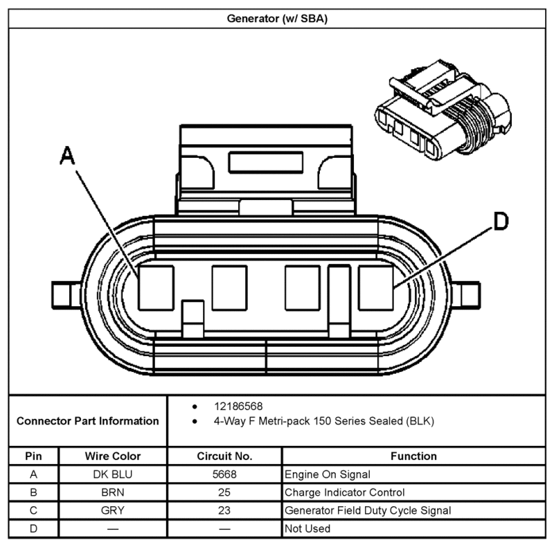 Vette and Truck Alt Wiring: 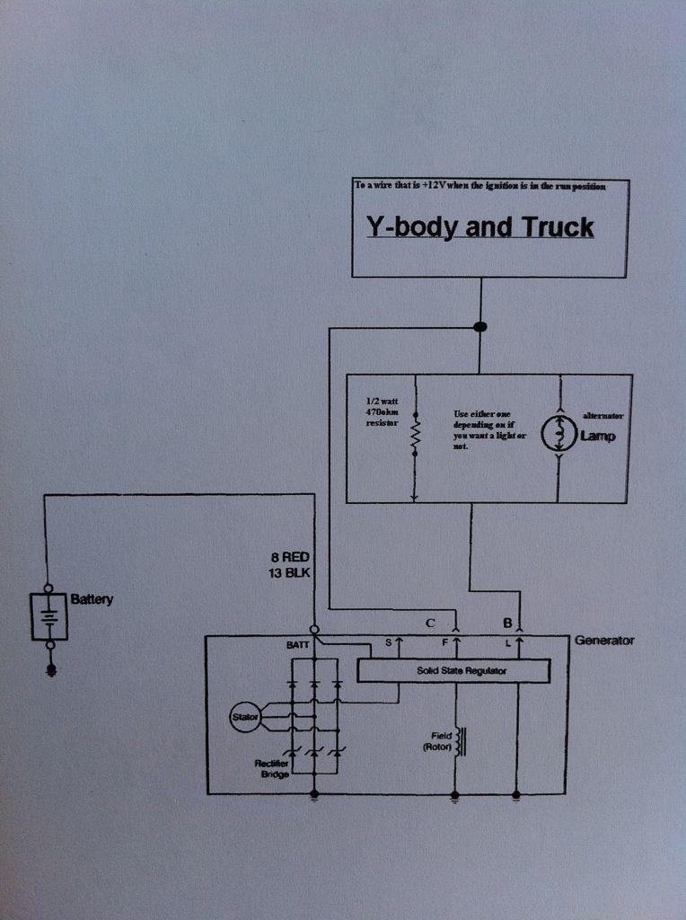 Basically you have two wires coming from the alt connector, one wire goes straight to 12 volt (Pin C), the other MUST have resistance, ie gen light or resistor (Pin B). 99' - '02 F Body Alt Wiring: 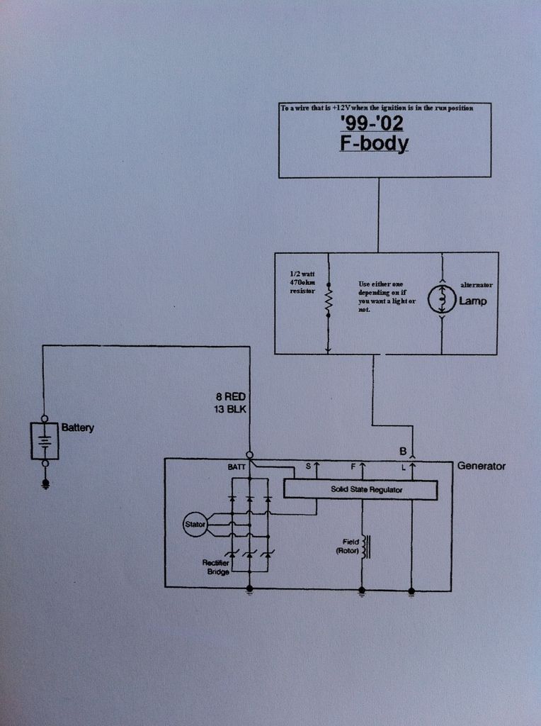 You only have one wire from the Alt (Pin "B") which goes through a "gen" light and then to the PCM. Be sure to include this light. Many people burn up alts by not doing this. Some information on wiring of the alt - This is from my BMW LSx swap so ignore the BMW bits.  Hope this helps... I know that the Alt seems to be one of those things that everyone has a different approach. I was hitting my head on my desk for a while on that one. Finally just got the service manuals out and looked at the wiring diagrams.
__________________
'55 3200 283 4 speed '68 Pontiac Firebird Poncho powered with a 6 speed |
|
|
|
|
05-05-2012, 07:58 PM
|
#14 |
|
Registered User
Join Date: Nov 2011
Location: Idaho
Posts: 857
|
Re: Ls alt wiring
Thanks on the lamp indicator any lamp will work?
Posted via Mobile Device |
|
|
|
|
05-05-2012, 11:48 PM
|
#15 |
|
Registered User
Join Date: Dec 2009
Location: Independence Mo
Posts: 4,118
|
Re: Ls alt wiring
What engine and.harness and year is it you're using? If its a truck harness, the two small wires go directly to the PCM, nothing has to be done.with them
Posted via Mobile Device
__________________
My '72 short bed build. http://www.ls1tech.com/forums/conver...6-0-4l80e.html 5.3 swap into my RUSTY '71 C10 http://ls1tech.com/forums/conversion...71-c-10-a.html |
|
|
|
|
05-06-2012, 09:30 AM
|
#16 |
|
Registered User
Join Date: Nov 2011
Location: Idaho
Posts: 857
|
Re: Ls alt wiring
06. Dbw Chevy Tahoe
Posted via Mobile Device |
|
|
|
|
05-06-2012, 08:21 PM
|
#17 |
|
Senior Member
Join Date: May 2009
Location: Fort Worth, TX
Posts: 6,370
|
Re: Ls alt wiring
A 2006 would have a "generator control module W/ amp probe" mounted on the negative battery cable. Your system will work without it...But its hard on the alternator.
|
|
|
|
|
05-06-2012, 09:48 PM
|
#18 |
|
Registered User
Join Date: Nov 2011
Location: Idaho
Posts: 857
|
Re: Ls alt wiring
Eliminated that system and rewired as per lt1 swap will that still be hard on the alternator
Posted via Mobile Device |
|
|
|
|
05-07-2012, 08:57 AM
|
#19 |
|
Registered User
Join Date: Apr 2012
Location: Memphis, TN
Posts: 65
|
Re: Ls alt wiring
I'm interested to hear about this, since this is a first that I have heard of it being hard on the alternator.
__________________
'55 3200 283 4 speed '68 Pontiac Firebird Poncho powered with a 6 speed |
|
|
|
|
05-07-2012, 07:02 PM
|
#20 | |
|
Senior Member
Join Date: May 2009
Location: Fort Worth, TX
Posts: 6,370
|
Re: Ls alt wiring
Quote:
|
|
|
|
|
|
05-07-2012, 08:05 PM
|
#21 |
|
Registered User
Join Date: Nov 2011
Location: Idaho
Posts: 857
|
Re: Ls alt wiring
I used the the lt1 swap site. Specifically I used the truck 2004 schematic which matches my 2006 harness almost to a T my harness has the blue and green PCM connectors. The rewire had to do with the green connector. Basically I eliminated purple wire coming out of PCM going to gbcm then I took the brown wire coming out of the gbcm and pinned it into c2 connector (green) pin15 where the purple was. I also eliminated the gray wire coming out of the gbcm and put in c2 pin 75 this pretty much eliminated the gbcm. I had to back track what I did it took me a while I hope I explained it right all this info like I said got from lt1swap. Oh yeah the brn ang Gry wires come directly from PCM now.
Posted via Mobile Device |
|
|
|
|
05-07-2012, 08:35 PM
|
#22 | |
|
Senior Member
Join Date: May 2009
Location: Fort Worth, TX
Posts: 6,370
|
Re: Ls alt wiring
Quote:
Does it regulate? (Not just a certain voltage) So you wired it just like a 04? Was your PCM flashed for this, Or does it work with a 05/06 program? |
|
|
|
|
|
05-07-2012, 08:39 PM
|
#23 |
|
Registered User
Join Date: Dec 2009
Location: Independence Mo
Posts: 4,118
|
Re: Ls alt wiring
If the GBCM is unhooked the alternator will charge at a default of 13.8 volts, not sure thats 100% or not though. I was under the impression that the tune needed to be modified when the alternator is wired like the earlier ones.
__________________
My '72 short bed build. http://www.ls1tech.com/forums/conver...6-0-4l80e.html 5.3 swap into my RUSTY '71 C10 http://ls1tech.com/forums/conversion...71-c-10-a.html |
|
|
|
|
05-07-2012, 09:02 PM
|
#24 |
|
Senior Member
Join Date: May 2009
Location: Fort Worth, TX
Posts: 6,370
|
Re: Ls alt wiring
ls1nova71, After doing some digging, You are correct with the 13.8 VDC being the default. And that is 100% duty cycle, 90% is 15.5 VDC
 Chart & Info.... The generator battery control module monitors the generator performance though the generator field duty cycle signal circuit, the generator field control circuit, and the battery positive voltage circuit. The generator battery control module controls the generator through the generator field control, charge indicator control, circuit. The signal is a 5-volt pulse width modulation (PWM) signal of 128 Hz +/- 5% with a duty cycle of 0-100 percent . The duty cycle sent by the generator battery control module is limited between 36-90% . When the engine is turned OFF, the module will send 0% duty cycle, low voltage. When there is loss of class 2 communication with the powertrain control module (PCM), the module will send 100% duty cycle, 13.8 volts . The table shows the commanded duty cycle and output voltage of the generator. The generator provides a feedback signal of the generator voltage output through the generator field duty cycle signal circuit to the generator battery control module. The signal is a 5-volt PWM signal of 128 Hz with a duty cycle of 0-100 percent . Normal duty cycle is between 5-90 percent . Between 0-5 percent and 100 percent are for diagnostic purposes. |
|
|
|
|
05-07-2012, 09:38 PM
|
#25 | |
|
Registered User
Join Date: Dec 2009
Location: Independence Mo
Posts: 4,118
|
Re: Ls alt wiring
Quote:
__________________
My '72 short bed build. http://www.ls1tech.com/forums/conver...6-0-4l80e.html 5.3 swap into my RUSTY '71 C10 http://ls1tech.com/forums/conversion...71-c-10-a.html |
|
|
|
|
 |
| Bookmarks |
|
|


 Linear Mode

