
|
Register or Log In To remove these advertisements. |
|
|
|
|||||||
 |
|
|
Thread Tools | Display Modes |
 04-11-2014, 11:12 PM
|
#26 |
|
Registered User
Join Date: May 2013
Location: Houston Texas
Posts: 713
|
Re: Ford Windstar E-Fan Wiring Question
I guess you could connect it to which ever can you wanted
|

|

|
|
04-12-2014, 12:27 AM
|
#27 | |
|
Senior Member
 Join Date: Jul 2009
Location: Athens, AL
Posts: 499
|
Re: Ford Windstar E-Fan Wiring Question
Quote:
|
|
|
|
|
|
04-12-2014, 08:44 PM
|
#28 |
|
Senior Member
 Join Date: Dec 2012
Location: Los Banos CA
Posts: 2,705
|
Re: Ford Windstar E-Fan Wiring Question
Great thanks
__________________
1956 Chevy Bel Air 2 door 1956 Chevy 210 4 Door 1970 K20 LWB project the Hulk build w/Supercharged 4.8L-ly2/4L60E HULK BUILD 1970 C10 Yellow/White Deluxe LWB w/ 5.3L-LC9/6L80E 1968 K10 LWB Dark green my son calls it "THE HULK Jr"HULK JR *SOLD* GO  GO!!! GO!!!
|
|
|
|
|
04-12-2014, 09:02 PM
|
#29 |
|
Registered User
Join Date: May 2013
Location: Houston Texas
Posts: 713
|
Re: Ford Windstar E-Fan Wiring Question
Ok, spent a few hours trying to figure out why both fans won't turn on when needed.
 So I found both 1 and 2 relay work, but I don't know how to test #3 which is a 5 pin relay. If I have #3 hooked up correctly 87a should have 12 volts to it correct?? I have tried this but get no voltage out of 87a. Am I doing something wrong? |
|
|
|
|
04-12-2014, 09:11 PM
|
#30 |
|
Registered User
Join Date: Dec 2009
Location: Independence Mo
Posts: 4,118
|
Re: Ford Windstar E-Fan Wiring Question
87a on 3 will only have power when 1 is energized,, and the fan is on. If the fan is missing or unplugged, it won't.
__________________
My '72 short bed build. http://www.ls1tech.com/forums/conver...6-0-4l80e.html 5.3 swap into my RUSTY '71 C10 http://ls1tech.com/forums/conversion...71-c-10-a.html |
|
|
|
|
04-12-2014, 09:27 PM
|
#31 |
|
Registered User
Join Date: May 2013
Location: Houston Texas
Posts: 713
|
Re: Ford Windstar E-Fan Wiring Question
Just looked at it again, I am getting 3V out of 87a, could #3 relay be bad??
|
|
|
|
|
04-12-2014, 11:20 PM
|
#32 |
|
Registered User
Join Date: Dec 2009
Location: Independence Mo
Posts: 4,118
|
Re: Ford Windstar E-Fan Wiring Question
Relays are a switch, either on or off, so you shouldn't get 3 volts out of it. Could be because its going through the fan. Have you switched the relays around to see if it changes anything? Are you absolutley sure you have it wired right? Sounds like a wiring issue to me.
__________________
My '72 short bed build. http://www.ls1tech.com/forums/conver...6-0-4l80e.html 5.3 swap into my RUSTY '71 C10 http://ls1tech.com/forums/conversion...71-c-10-a.html |
|
|
|
|
04-13-2014, 01:32 AM
|
#33 |
|
Senior Member
Join Date: Dec 2012
Location: Los Banos CA
Posts: 2,705
|
Re: Ford Windstar E-Fan Wiring Question
I just finished up the fan wiring and wired as above and started the engine for the first time (well woth coolant). Fans worked great. Low speed and than high speed. So the diagrams definitely works
Thanks guys
__________________
1956 Chevy Bel Air 2 door 1956 Chevy 210 4 Door 1970 K20 LWB project the Hulk build w/Supercharged 4.8L-ly2/4L60E HULK BUILD 1970 C10 Yellow/White Deluxe LWB w/ 5.3L-LC9/6L80E 1968 K10 LWB Dark green my son calls it "THE HULK Jr"HULK JR *SOLD* GO GO!!!
Last edited by First c10; 04-13-2014 at 02:07 AM. |
|
|
|
|
04-13-2014, 02:07 AM
|
#34 | |
|
Senior Member
Join Date: Jul 2009
Location: Athens, AL
Posts: 499
|
Re: Ford Windstar E-Fan Wiring Question
Quote:
If you can disconnect the control wires from the PCM, turn the ignition on with the engine off. If you ground the green wire in the diagram (fan control 1) both fans should run at half speed. If you ground both the green wire and the blue wire at the same time, both fans should run at high speed. If the fans work as described above when disconnected from the PCM, then your problem is with the PCM programming or control wiring. If you get any other behavior, the problem is with the relay or fan wiring. |
|
|
|
|
|
04-13-2014, 11:07 AM
|
#35 |
|
Registered User
Join Date: May 2013
Location: Houston Texas
Posts: 713
|
Re: Ford Windstar E-Fan Wiring Question
Thanks for everyone's help. I double and triple checked the wiring and all is just as diagramed. I turn the ignition on engine off and can only get the first fan to turn on. This only turns on if I touch #85 from both relay 1 & 3 to a ground. I can't get the second fan to turn on at all even if I ground all 3 85's?? Yes, both fans work.
I'm thinking #3 5 pin relay is broken. It clicks but won't put out voltage. |
|
|
|
|
04-13-2014, 12:24 PM
|
#36 |
|
Senior Member
Join Date: Jul 2009
Location: Athens, AL
Posts: 499
|
Re: Ford Windstar E-Fan Wiring Question
Which fan turns on in reference to the diagram that you posted? I know it's physically the smaller fan, but is it the one on the left or the right in the schematic?
|
|
|
|
|
04-13-2014, 12:40 PM
|
#37 |
|
Registered User
Join Date: Dec 2009
Location: Independence Mo
Posts: 4,118
|
Re: Ford Windstar E-Fan Wiring Question
My guess it's going to be the fan on the right that's coming on.
So if you ground just 85 of relay 1 nothing happens? Try swapping relay 2 and 3, and ground 85 of relay 1, if they both come on low, then replace the 3 relay. Pin 87a on 3 may not be working. Edit- The more I look at it, this probably isn't going to help. Are you sure the fan on the left is plugged in and works? It seems like the open in the circuit is there.
__________________
My '72 short bed build. http://www.ls1tech.com/forums/conver...6-0-4l80e.html 5.3 swap into my RUSTY '71 C10 http://ls1tech.com/forums/conversion...71-c-10-a.html Last edited by ls1nova71; 04-13-2014 at 12:46 PM. |
|
|
|
|
04-13-2014, 01:02 PM
|
#38 |
|
Registered User
Join Date: May 2013
Location: Houston Texas
Posts: 713
|
Re: Ford Windstar E-Fan Wiring Question
I'm am positive both fans work, I have switched ray 1 & 2 and then only the left fan will turn on. Only thing I can think of is 87a is dead.
|
|
|
|
|
04-13-2014, 01:37 PM
|
#39 |
|
Senior Member
Join Date: Jul 2009
Location: Athens, AL
Posts: 499
|
Re: Ford Windstar E-Fan Wiring Question
Ben,
In post #35, you said that only one fan comes on when you ground the control line (pin 85) of relays 1 and 3. In post 38, you said the fan that comes on is the one on the left in the diagram. I'm making one assumption (so tell me if it's wrong). The assumption is that relay 2 and 3 still have their control lines (85) wired together. So when you ground the control for 3, you're also turning on relay 2. If that's the case, then the problem is either: 1) The fan on the right in the diagram is bad. 2) Relay 1 is bad 3) The normally closed contact on relay 3 is bad 4) The wiring from pin a of the fan on the right to pin 30 of relay 3 is open 5) The wiring from pin b of the fan on the right to pin 87 of relay 1 is open 6) The wiring from pin b of the fan on the left to pin 87a of relay 3 is open You've assured us that "1" and "2" above are covered. To test number 3, pull the 5 pin relay (3) out of the circuit. Plug a jumper wire into the relay 3 socket to short pin 30 to pin 87a. Turn the ignition on and ground the control line (pin 5) of relay 1 only. If both fans come on, the problem is relay 3. If both fans still don't come on with the above test, leave the jumper in place in the relay 3 socket. Ignition on, engine off, ground the control line (85) for relay 1 only. Measure the voltage between a good ground and all the following connections. 1) pin 30 of relay 1 2) pin 87 of relay 1 3) pin B of the fan on the right 4) pin A of the fan on the right 5) pin 30 of relay 3 (even though there is a jumper still in the socket) 6) pin 87a of relay 3 7) pin B of the fan on the left Then post what all those voltages readings are. |
|
|
|
|
04-13-2014, 04:04 PM
|
#40 |
|
Registered User
Join Date: May 2013
Location: Houston Texas
Posts: 713
|
Re: Ford Windstar E-Fan Wiring Question
Thanks dayj1, will do, just won't be home for a while. You are correct, post 35 the relays are connected just like the diagram and only the fan on the right of the diagram will turn on.
Post 38, I switched wiring between relay 1 & 2 which then turned the fan on the left on. You are correct that relay 2&3 #85s are wired together and I will test 3 as suggested and repot findings. Thanks again for all your help!! |
|
|
|
|
04-13-2014, 08:30 PM
|
#41 |
|
Registered User
Join Date: May 2013
Location: Houston Texas
Posts: 713
|
Re: Ford Windstar E-Fan Wiring Question
Question before I try the test. Your saying to connect pin 30 and pin 87a of relay 3 together?
|
|
|
|
|
04-13-2014, 08:50 PM
|
#42 | |
|
Senior Member
Join Date: Jul 2009
Location: Athens, AL
Posts: 499
|
Re: Ford Windstar E-Fan Wiring Question
Quote:
|
|
|
|
|
|
04-13-2014, 09:30 PM
|
#43 |
|
Registered User
Join Date: May 2013
Location: Houston Texas
Posts: 713
|
Re: Ford Windstar E-Fan Wiring Question
Tested out and this is what I got
1) pin 30 of relay 1 12+ 2) pin 87 of relay 1 11.5 3) pin B of the fan on the right 11.5 4) pin A of the fan on the right 11.5 5) pin 30 of relay 3 (even though there is a jumper still in the socket) 0.1 6) pin 87a of relay 3 0.1 7) pin B of the fan on the left 1.5 Also, I tested relay 5 this way https://www.youtube.com/watch?v=vupmb2U-shk In the vid it shows an on and off switch. with the switch on pin 87 received power. With switch off pin 87a received power. When I hooked it up like the vid both fans turned on, there was no one or the other?? Is my relay shot? |
|
|
|
|
04-13-2014, 10:29 PM
|
#44 | |
|
Senior Member
Join Date: Jul 2009
Location: Athens, AL
Posts: 499
|
Re: Ford Windstar E-Fan Wiring Question
Quote:
Just to confirm, you had everything hooked up like your original diagram except that relay 3 was removed from the circuit (with a jumper from pin 30 to pin 87a in the socket) and the fan control lines were disconnected from the pcm (and you manually grounded the fan 1 control only). Right? When you followed the steps above, you were following the current flow (from right to left) in the diagram that you posted to check out the wiring. You got a full 12 volts at terminal 30 of relay 1. That's perfect. You got 11.5 at terminal 87 of relay 1. That's OK. It looks like you lost 0.5 volt in the relay contact which is a lot greater than the normally accepted 0.1 volt per connection. Long term the relay may run a little warm, but it isn't causing the problem at hand. You got 11.5 at terminal B of the fan on the right. That's perfect, you didn't lose anything through your wiring to the fan. You got 11.5 at terminal A of the fan on the right. If the fans were running, you'd have seen a significant voltage drop here. The copper windings in fan motor act electrically as a resistor, but their resistance is pretty low (just a few ohms) so the voltage drop across a non running fan shouldn't be more than a fraction of a volt. You got 0.1 volt at pin 30 of relay 3. I believe that you just found your problem! Check the wire between terminal A of the right fan and pin 30 of relay 3. It's either broken or has a bad connection. Fix that, plug relay 3 back in (after you remove the jumper), turn the ignition on, cross your fingers, and ground the fan 1 control wire for another test. |
|
|
|
|
|
05-14-2014, 12:34 PM
|
#45 |
|
Senior Member
Join Date: Dec 2012
Location: Los Banos CA
Posts: 2,705
|
Re: Ford Windstar E-Fan Wiring Question
Does anyone have a wiring diagram for this 3 relay setup and adding a trinary switch to control the fans when the AC is on?
I got my AC up and running but need the fans to come on when in traffic or parked. Since the low/high speed as wired above is how mine is wired and works great just wondering the best way to wire the trinary switch into the mix? thanks Scott
__________________
1956 Chevy Bel Air 2 door 1956 Chevy 210 4 Door 1970 K20 LWB project the Hulk build w/Supercharged 4.8L-ly2/4L60E HULK BUILD 1970 C10 Yellow/White Deluxe LWB w/ 5.3L-LC9/6L80E 1968 K10 LWB Dark green my son calls it "THE HULK Jr"HULK JR *SOLD* GO GO!!!
|
|
|
|
|
05-14-2014, 01:05 PM
|
#46 | |
|
Senior Member
Join Date: Jul 2009
Location: Athens, AL
Posts: 499
|
Re: Ford Windstar E-Fan Wiring Question
Quote:
|
|
|
|
|
|
05-14-2014, 01:27 PM
|
#47 |
|
Senior Member
Join Date: Dec 2012
Location: Los Banos CA
Posts: 2,705
|
Re: Ford Windstar E-Fan Wiring Question
dayj1
Thanks for the information that is what I was thinking (well something along those lines) no worries on the time frame. I don't need it today. Due to the high/low speed 3 relay system I was a little worried about the codes and possibly damaging something. Thanks Scott
__________________
1956 Chevy Bel Air 2 door 1956 Chevy 210 4 Door 1970 K20 LWB project the Hulk build w/Supercharged 4.8L-ly2/4L60E HULK BUILD 1970 C10 Yellow/White Deluxe LWB w/ 5.3L-LC9/6L80E 1968 K10 LWB Dark green my son calls it "THE HULK Jr"HULK JR *SOLD* GO GO!!!
|
|
|
|
|
05-16-2014, 10:40 AM
|
#48 |
|
Senior Member
Join Date: Dec 2012
Location: Los Banos CA
Posts: 2,705
|
Re: Ford Windstar E-Fan Wiring Question
Any luck with the diagram?
__________________
1956 Chevy Bel Air 2 door 1956 Chevy 210 4 Door 1970 K20 LWB project the Hulk build w/Supercharged 4.8L-ly2/4L60E HULK BUILD 1970 C10 Yellow/White Deluxe LWB w/ 5.3L-LC9/6L80E 1968 K10 LWB Dark green my son calls it "THE HULK Jr"HULK JR *SOLD* GO GO!!!
|
|
|
|
|
05-16-2014, 05:40 PM
|
#49 | |
|
Senior Member
Join Date: Jul 2009
Location: Athens, AL
Posts: 499
|
Re: Ford Windstar E-Fan Wiring Question
Quote:
 . . Here's the basic function of a trinary switch:  The dark green A/C clutch wires are easy. I assume that you have a power wire going to your A/C clutch already. For a GM vehicle, it's usualy dark green (ironic, I know). If you cut the wire going to your clutch, you have 2 ends. One end goes to one green wire on the trinary and the other end goes to the other green wire from the trinary, Easy and no magic required. The fan control wires on the trinary switch are not quite as easy when you throw multiple fans, dual speeds, and PCMs into the mix. I know you didn't ask for all this, but I'm long winded .To get started, here's a really dumbed down picture of the PCM control of a fan relay. It doesn't even show the fan, because what the relay is controling is irrelevant at this point: 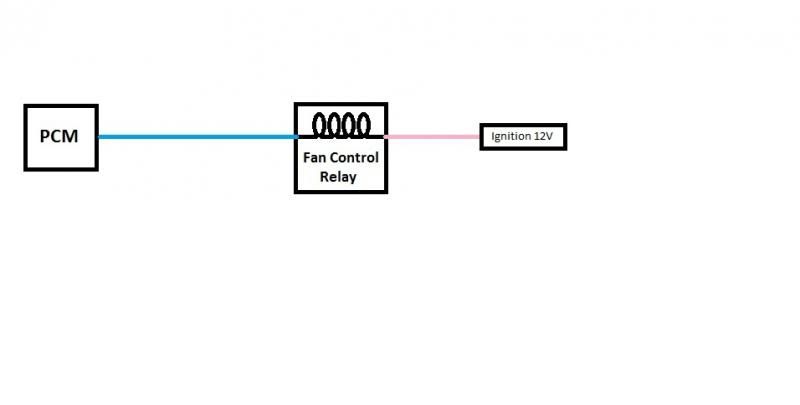 Here's the same picture, but I added the trinary switch. 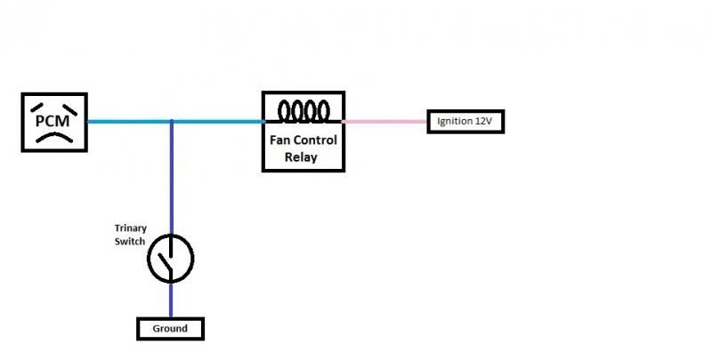 The trinary switch will control the fan as intended, but the PCM is not happy. You can literally see the frown in the picture . Why is that? Well, the PCM periodically runs diagnostics on the fan control circuit. Since all that is between the fan control line(s) and 12V is the coil of a relay, the PCM should see a voltage on the fan control line because, electrically, the relay coils is just like a resistor. If the trinary switch closes, and forces that line to ground, the PCM sees the ground (0 Volts) and turns on your check engine light. To make things even more interesting, the default behavior when the PCM sees a fault with the fan control is to turn both fans on high speed all the time! This is not what we want.How do we stop the trinary switch from upsetting the PCM? We can use a diode which is the electrical equivalent of a one-way valve. The band on the diode (the cathode side) needs to point to the more negative part of the circuit if you want electricity to flow through it. It looks like this:  In the picture above, the PCM is still not happy even though we added the diode to block the trinary switch's ground signal from getting to it. The problem now is that the diode also blocks the PCM's abilty to "see" the relay coil (even though the PCM can still control the relay by switch ing ground on the control line). The fix for that is a pull-up resistor. 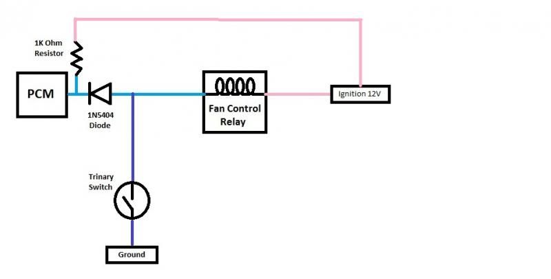 The picture above works because the PCM sees the pull up resistor and thinks it is the fan relay coil. So, the diagnostics pass. I didn't actually draw what it would look like to add in the additonal high speed fan relays, but it would require a total of 4 diodes and 2 resistors to make it all work. It's not that big of a deal, but I'm picky about such things and there is a "better" way. On to the next diagram: 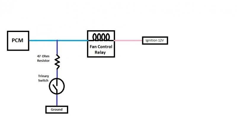 The picture above shows 1 resistor in series with the trinary switch. It's value of 47 ohms was selected for a couple of reasons. First, 47 Ohms is a common value for a resistor and its available at Radio Shack which almost everyone has nearby. 50 (or 40) would work just as well, but you would have to special order those. Second, and probably more importantly, most 12 volt relay coils are going to have a resistance of about 80-90 ohms. 47 is about half of the relay coil resistance (or 1 third of the total resistance of the coil plus the resistor). Since voltage, current, and resistance are all proportional to each other, we can calculate that the resistor will eat up about 4 of the 12 volts leaving 8 for the relay. 8 volts is still enough to operate the relay and, at the same time, hold the control line above ground potential so that the pesky fan control diagnostic test passes! For anybody that's still awake, here's what you get when you add the high speed relays back to the picture: 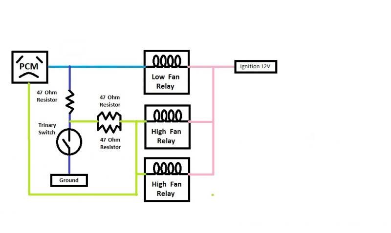 In the picture above, I drew the PCM as unhappy. I've never tried that particular combination, though. In theory, the A/C trinary switch will turn both fans on high and the PCM will pass the diagnostic as expected. But, the possibility is there that the when the PCM tries to turn on low speed, both fans will come on at high speed. The reason is that the trinary switch ties together the low speed and high speed control wires together. Since the low control would have to go through all 3 resistors to get to the high speed relays, the voltage drop might be enough to prevent that from happing. It's just to close to call and intermittent at best. To fix the problem, we need our diodes again to direct the signal from the trinary switch to the high and low controls without tying them together, like this:  So, the diagram above makes everyone happy. The PCM passes its diagnostics and the trinary switch can do it's thing. It is the most "correct" way to do it that I've presented here. It works like this: 1) When the trinary switch closes (A/C line pressure is high) both fans run at high speed (engine temp is irrelevant). 2) Both fans run at half speed when engine temp is between low speed fan temp and high speed fan temp and A/C line pressure is low. 3) Both fans run at full speed when engine temp is above high speed fan temp (A/C pressure is irrelevant). Here's one last diagram to show the way that I personally wire the trinary switch on my conversions.  It is really simple as far as the actual wiring goes and it keeps the PCM happy. But, it only kicks on one fan (at full speed) if the engine coolant temp is below the low speed threshold and the trinary switch closes. You aren't likely to encounter this scenario outside of when you first crank the truck (with the A/C on) before it gets to operating temp. It doesn't hurt anything, it's just a little different. It's a price I've always been willing to pay for simplicity in the wiring. Let me know if you have any questions. |
|
|
|
|
|
05-16-2014, 06:03 PM
|
#50 | |
|
Senior Member
Join Date: Dec 2012
Location: Los Banos CA
Posts: 2,705
|
Re: Ford Windstar E-Fan Wiring Question
I have to say that was worth the wait. Your explanations were great. I have a question regards to diagram 2 and the last diagram. Aren't they the same but with only one 47 ohm resister and coil?
In my mind I was thinking the last diagram but to the low speed instead. I didn't think about high which would be better but don't you have to have the low speed relay grounded by the PCM to get high speed ground to work? Oh but you said only one fan would be high!!! Oh I will go check my diagram. Great post!! You definitely sound like you have worked on this before. Thanks for the info. I will check that out. Thanks Scott Quote:
__________________
1956 Chevy Bel Air 2 door 1956 Chevy 210 4 Door 1970 K20 LWB project the Hulk build w/Supercharged 4.8L-ly2/4L60E HULK BUILD 1970 C10 Yellow/White Deluxe LWB w/ 5.3L-LC9/6L80E 1968 K10 LWB Dark green my son calls it "THE HULK Jr"HULK JR *SOLD* GO GO!!!
|
|
|
|
|
|
| Bookmarks |
|
|


 Linear Mode

