FUEL LINE (2 of 6)
CHECKING THE HARDWARE
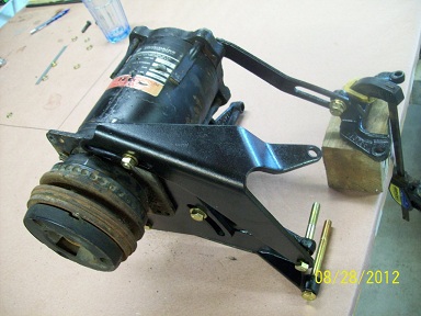
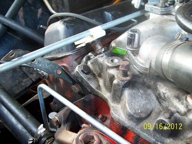
When the order arrived, so did the first problems. I had intended to fasten the regulator directly to the filter/inlet housing with a 3/8 NPT nipple (see the picture above). However, it turned out there wasnt sufficient space to get 3/8 tubing into the bottom of the regulator due to a conflict with the vacuum tree fitting on the intake manifold. Also, service replacement of the fuel filter was complicated. I concluded Id have to mount the regulator elsewhere.
Another problem was making a 37 degree flare with the tool that I bought from Summit. The tool would not hold the 3/8 steel tube in place when I attempted to flare the end. So I sent the tool and the AN fittings back (full refund) and abandoned the 37 degree flare idea. Since I already had a decent KD Tools 45 degree flaring tool, I then considered using single flare SAE 45. However, as I read through literature on flared tubing, I learned that single flare tubing connections are less resistant to vibration and more prone to crack than double flares. The only reason I had been avoiding double flares until now was because I was having a hard time finding the correct NPT to inverted flare adapter. This part can be found, I said to myself. So I went back to square one and stuck with my original goal of using double flares at the ends of the tubing.
Here is a good summary of the differences between the two types of flare.
I finally found a supplier and ordered the 3/8 M-NPT x 3/8 tube inverted flare adapter fittings. I also bought two straight five foot sticks of 3/8 tubing with prefabricated flares and tube nuts at both ends that would be used for the final installation (the coiled stuff is hard to get nice and straight). I would cut off the prefabricated flares and use the tube nuts on my own flares.
While waiting for the fittings, I looked for a suitable location for the regulator. I decided to mount it to the inlet manifold at the front of the engine. In this location, it would act as a 90 degree transition for the tubing (vertical from pump, then horizontal to carburetor) and would require two sections of tubing. I made brackets out of wood to help locate the regulator and design the support bracket. I also considered clearances needed for future installation of the stock air conditioning compressor brackets by referring to a mockup I made up.
AC bracket mockup used for reference.
BENDING THE TUBING
Once I had a fix on the regulator location and bracket configuration, I started to work on bending the 3/8 steel tubing. I discovered immediately (not to my surprise) that my $6.99 Harbor Freight bender wasnt going to cut it. After some research, I bought a Ridgid Model 406 for use only with 3/8 tubing. As soon as it arrived I made a few trial bends. A good tool sure makes a difference ! On 180 degree bends, a slight flattening was noticeable on the outer circumference, but otherwise, nice smooth bends.
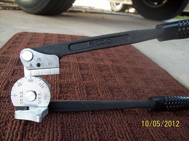
A fine bender, indeed.
I had about five feet of 3/8 coiled tubing and a few other pieces on hand that I used for practice bends. I took my time and made a lot of measurements. I tried using the stiff wire method to make templates but they werent accurate enough. I got the best results by trial and error using actual tubing and measuring the results. Eventually I got the dimensions and procedure down so I took one of my straight pieces of tubing and bent and flared the fuel pump outlet end. I only made enough bends so that it stuck up vertically near the water pump. Next I went to work on the tubing coming from the filter/inlet housing. Similar to the pump end, I made bends only so far as to get the tubing past the carburetor. With the ends of the two tubing sections flared and fastened in place at their ends, I could mark the locations of the final bends so they would accurately mate to the regulator.
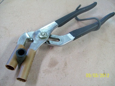
I made this tool to pinch off the inlet hose to the pump and
cut off the fuel supply while everything was disconnected downstream.
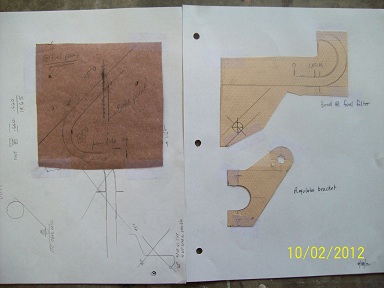
Left: final dimensional drawing for the tubing at the pump outlet
Upper right: final dimensional drawing for the tubing at the filter/inlet housing
Lower right: template for regulator bracket
Here are the two tubing sections before making the final bends into the regulator.
The regulator bracket attaches where the bolt sticks up on the manifold.
The tubing needed to clear the thermostat housing bolt. The socket
helped me figure out the position of the regulator so the bolt will be accessible.