TEMPERATURE SENDER REVISITED
I needed the ½" NPT port on the passenger side of the intake manifold for the heater hose connection. However, it was occupied by the temperature sender (see my Post #20). I wanted instead to use the 3/8" NPT port in the driver side cylinder head. However, the parts books call for a sender with a ½" NPT connection for this application. I figured I could find something of equivalent performance in 3/8" NPT so I searched through the Echlin catalog until I found a sender of a resistance range that was close to the specified TS6469. I found a TS6729 that came pretty close.
TS6469
...368 ohms @ 100 deg..
80 ohms @ 220 deg.
Range=288 ohms
(1/2" NPT-button)
TS6729
...
339 ohms @ 100 deg
..35 ohms @ 220 deg
.Range=304 ohms
(3/8" NPT-stud)
Difference.
..29 ohms @ 100 deg
...45 ohms @ 220 deg
.
..
16 ohms
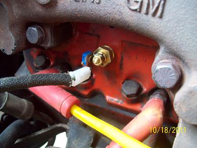
I obtained a TS6729 and installed it. I started the engine cold, and watched the gauge needle head toward hot very quickly and nearly peg after just a few minutes of engine operation. Upon further research, I discovered that one solution to temperature sender range problems is by adding an inline resistance. Like this one for example - - - >
http://www.parts123.com/parts123/yb....Z5Z5Z50000050#
Based on my comparision of the specified TS6469 sender versus the proposed TS6729, I figured that adding 50 ohms would make it work OK. I went to Frys and bought a couple of trimpots and several values of fixed resistors so I could experiment and find a good value to use. Then I made up an assembly using a 100 ohm trimpot mounted on a surplus terminal board I had on hand, some solid wire and solder, and epoxy to hold the parts together and insulate everything.
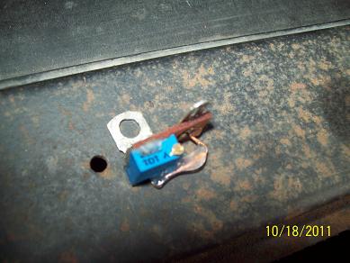
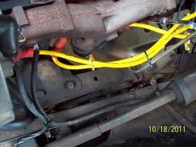
The old loom covering the sender wire was shot so I installed a new loom over it. I rerouted the sender wire and secured it.
I set the trimpot to 50 ohms and installed it inline with the new sender and then started a cold engine. I waited until the engine was fully warmed up and then adjusted the trimpot until the needle was almost above the R in TEMPERATURE. I later measured this trimpot resistance at 41 ohms.
With this arrangement, the needle on the temperature gauge at fully warmed up is almost to halfway. I like it in this position better than before. The needle also moves off cold sooner, probably because the sender is in the head and not in the manifold. With the trimpot installed, I can adjust the resistance and get the gauge to where I feel it gives the best indication. I intend to replace the trimpot later with a fixed inline resistance for a more secure installation under the hood.
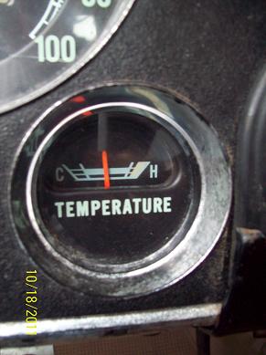
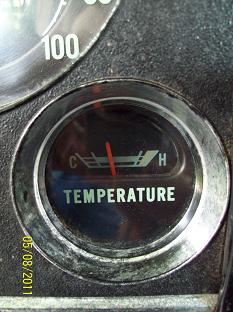
Fully warmed up with TS6729 and trimpot at 41 ohms, the needle is above the R
Same operating temperature with TS6469, the needle was above the E
With the sender relocated, I had a place to connect the heater hose to the intake manifold.
Temperature sender TS6729
$..16.24
Resistors
.........
..9.51
Electrical terminals
.
.....
.
..6.47
Total
...........
$..32.22