My son Brian came over a while back and we spent a day thinning out that huge S10 wiring harness. We got pretty much all of the stuff out of it that we planned, except for the ABS brakes. I did however test it a few days later by simply unplugging the unit completely and that seemed to have no impact at all on the PCM, so for now I have removed the ABS module (which is enormous) and I will get rid of those wires in the future after some test driving. Heres a pile of stuff we eliminated from the harness:

I was hoping to remove a lot more, but every little bit helps when cramming stuff under a dash. I will do a test routing soon, and when I am happy with the harness routing I will clean things up and add a protective layer to the various bundles of wire.
Before reinstalling the cab, I finished off a couple of things that would be far easier to do while access was good. The first item was the windshield. I fabbed up a hand crank system to open and shut the windshield, but I still need to find a decent handle and then install the works (pics to follow once I have it all buttoned up).
Next came the floor. The entire central floor section was missing when I bought the truck and I have no idea what they looked like (or even what they were made of), so I just took a guess and fabbed up a new one, then hit it with a coat of black paint and tossed it in:


The new header panels that I made earlier this year were welded in place:

I took advantage of the easy access to the engine in order to install a temperature controller for the electric fan. Skymangs had suggested the type that screws into the water jacket in the cylinder head, rather than the types that you stick into the fins of the rad, or down into a rad hose. The GM 4.3 has an unused threaded hole in the passenger side cylinder head, so thats what I used. It's sealed from the factory with a 5/16 female square pipe plug, which is quite clever. If they had used a ¼, ⅜ ths or ½ inch plug then everybody in the world with a ratchet would be able to take that plug out! Luckily I had an old ½ inch square plug wrench, and with the help of a grinder I whittled the end down to 5/16ths. Heres a pic of the new sender, the old plug, and the new tool:

The plug itself is hidden by the oil pan dipstick, so the dipstick had to be shifted away and a bit of heat was required to break the old plug free. The new sender needs to be able to accept a wire connection, so the dipstick had to be modified to move it over a bit. The quickest way to do this was to slice the bracket that holds the dipstick in place, and add a bit of metal to move the dipstick out of the way of the sender. A few minutes later it was done. Heres a before & after:


I drilled and tapped holes in the rad cradle to securely route the rubber transmission lines, and did the same for the electric rad fan wires (boring stuff so no pics taken).
My rad cradle sits on some thick tube steel thats welded to the frame, and I have since read a few posts that suggested some sort of cushion in order to minimize the transmission of vibrations into the cab, so I made and installed a pair of rubber spacers:

Hopefully these will help with noise and vibration (while the cab sits on rubber cushions, the front end sheet metal bolts to the cab).
There are a number of things on my to do list that are far easier to visualize with the body panels installed, rather than taking tricky measurements. My brother was available to help, so we got the main body panels in place. I then spent some time aligning panels and adjusting heights to get things straight and square. My brother and I had used some wooden supports to set the running boards to height, and I could now install the running board mounts. Simple design, nothing fancy, but nice & thick! They are temporarily bolted in while I verify their final height and how I am going to deal with the wooden spacers that sit between the boards and the mounts.

The running boards are currently about ¾ inch above their mounting brackets, and these trucks originally came with wooden spacers that filled this gap. Im not worried about weight, and I want strong running boards, so I will cut some ¾ inch wood planks that run the length of the boards. This will fill the ¾ gap, and provide support everywhere when people get in & out of the truck.
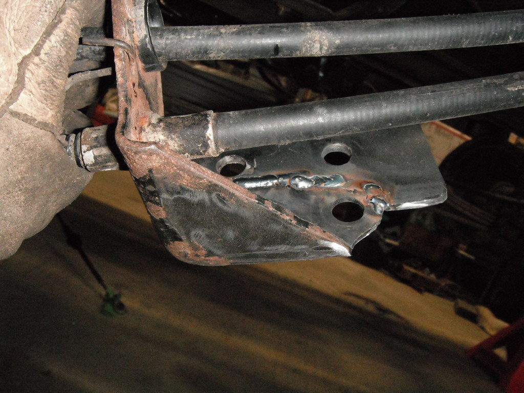
Once my running boards were in place, I noticed some very slight interference with the rear parking brake cable mount and I also saw that one of the parking brake cables would be rubbing on a body mount. To address this I simply extended the rear cable support downwards about an inch by welding on a piece of metal and drilling 2 holes:
I then tried to figure out how & where to mount the pedal assembly. I found this to be a bit of a juggling act to do alone, and some of it hinged on exactly where I would mount the front cable bracket support on the frame. Remember that EVERYTHING has been moved around. The new cab is back 8 ½ inches and is raised up, the rear cable mount has been lowered and the rear axle has been slid forward 1 ½ inches. After a few frustrating tries, I opted to do this:
First I affixed a stud to a small plate, which I then tacked to the legs of the front cab mount:

Then I made a sliding bracket to snap the front parking brake cable into:

Then the bracket was installed on the frame. Its adjustable, and it allowed me to find that exact spot where that front cable mount should sit in order to allow the parking brakes to work properly. Its temporary, and once everything is set in place for the final time I will weld a permanent cable bracket in place:

This now gave me the chance to play with different orientations of the S10 pedal assembly. To get this right I first fabbed up a kick panel which (for now) is bolted in place. Depending on how I finish the interior, I may later remove the bolts and weld it in:

After playing around with different heights and angles, I eventually came up with an orientation for the S10 parking brake pedal assembly that would work for me. I used a fairly sturdy gauge of metal for the kick panel, so installing the parking brake assembly was just a matter of marking 3 holes and then welding nuts into the kick panel.

I still have to come up with a decent floor pass-thru for the parking brake cable. The S10 grommet is meant to come straight up from a horizontal floor, but in my application the floor is on a sharp angle and the S10 grommet will be a very poor fit.
More to follow!