
|
Register or Log In To remove these advertisements. |
|
|
|
|||||||
|
|
|
|
|
|
|
|
|
|
|
|
|
|
|
|
|
|
 |
|
|
Thread Tools | Display Modes |
|
|
 10-11-2012, 10:42 AM
|
#1 |
|
Boosted Member
Join Date: May 2002
Location: Mackinaw, IL
Posts: 2,200
|
Re: No Limit Wide-Ride C10 IFS 63-87
Rob...a few questions regarding my install on my wide-ride for my 72 K/5.
First a bit of feedback. The instructions that come with the kit are very lacking when it comes to specifics for the 63-87 kit. The printed instructions, as well as the DVD are centered around 50s chevy truck installations, which are significantly different than the later trucks (boxing plates, specific measurements, etc). As such, I've had to rely on the photos in this thread to guide me along thus far. http://67-72chevytrucks.com/vboard/s...=507066&page=2 1) Judging by these two photos, it appears as though I have the upper arms on backwards. My upper arm (driver side) 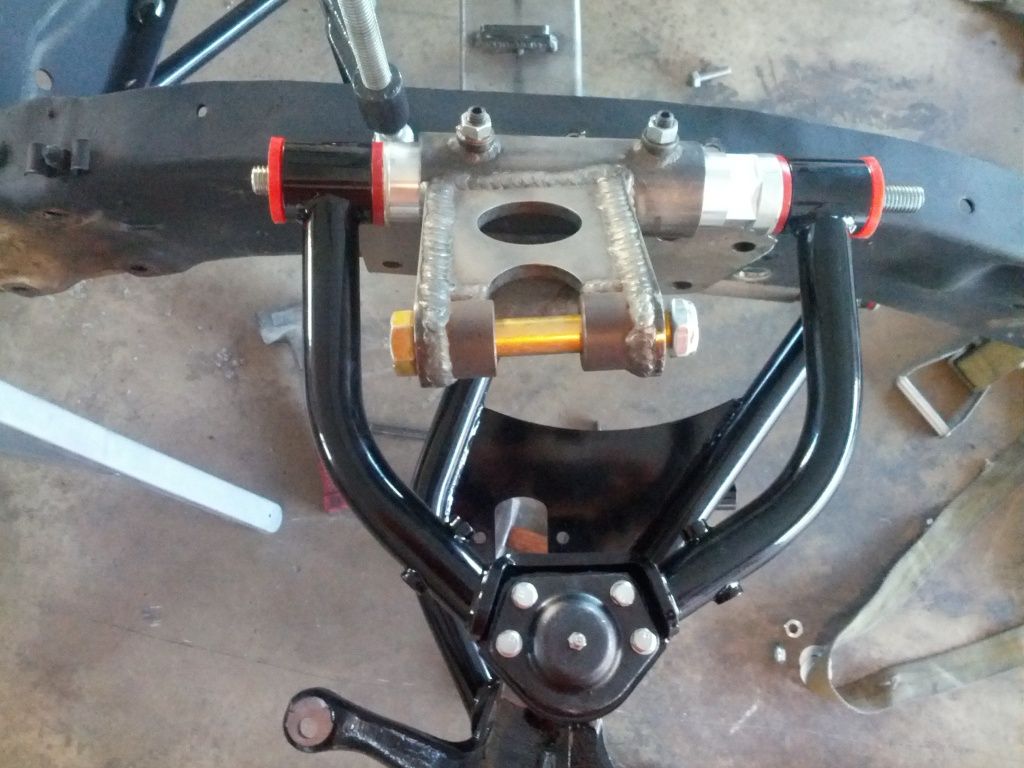 Can you confirm this is installed on the wrong side? 2) What is the wheel travel supposed to be for this suspension? I am only getting about 3-3.5" of vertical travel at the spindle shaft before the front of the lower arm contacts the crossmember and limits upward travel. On downward travel, the balljoint binds, and limits the travel. Thoughts? All the way "down" 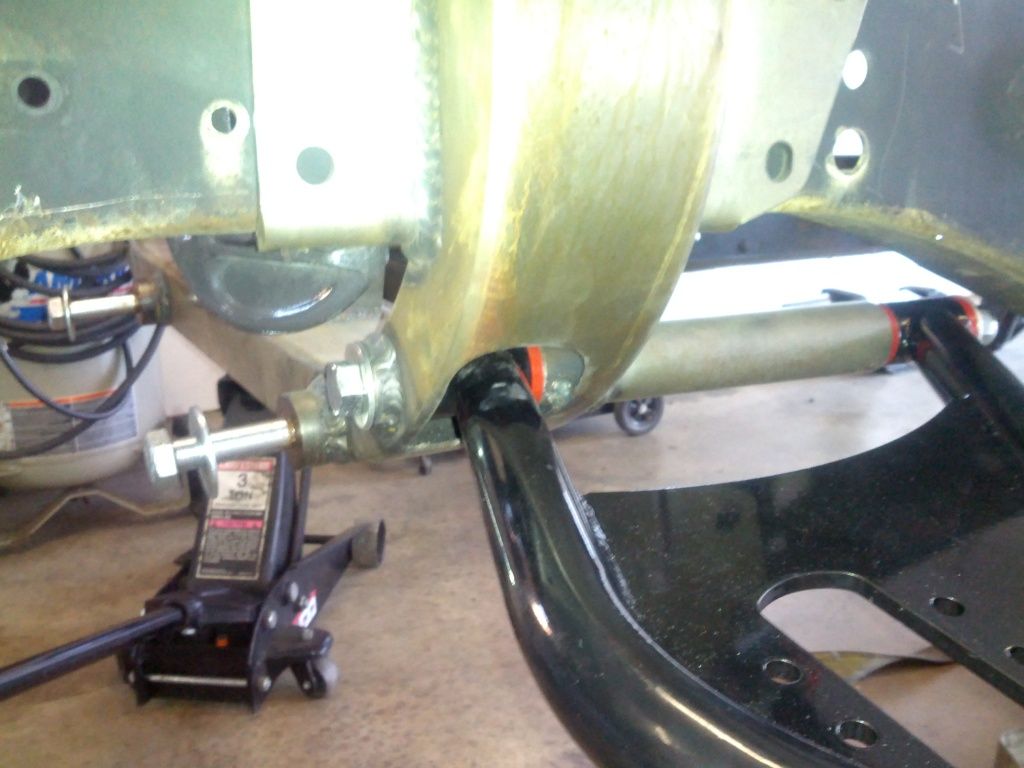 You can kind of see how the lower balljoint is binding up and limiting downward movement. 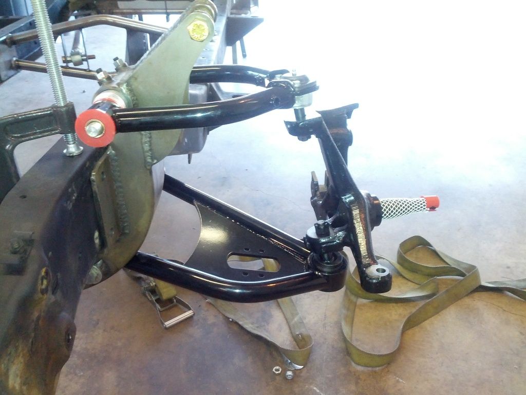 All the way "up" with the lower arm contacting the crossmember. 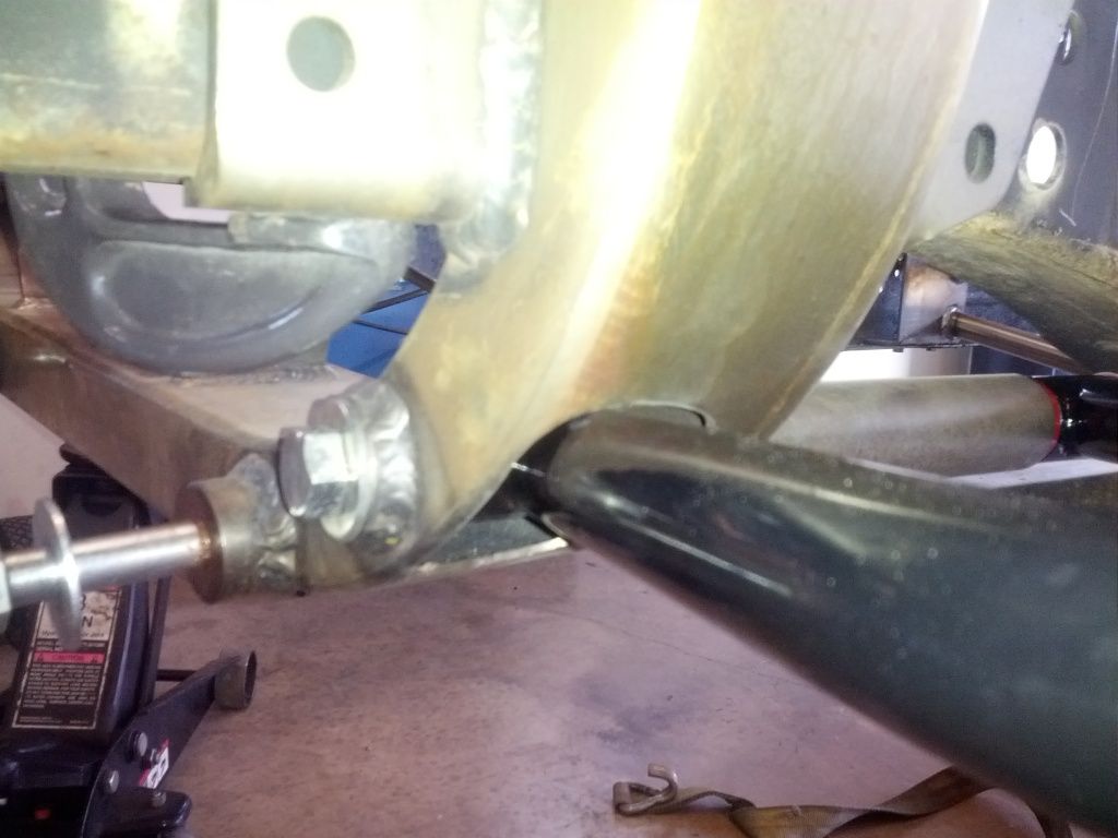 Like i mentioned, from all the way "down" to "up" the travel at the spindle shaft is about 3.5". Seems to me that it should be more? 3) I am mocking it up right now, with spindles attached, so that I can locate the crossmember relative to axle center line (there are no holes that line up, since this is a 4x4 frame). Is there a location on the crossmember that is coincident with the centerline of the spindle (wheel centerline)? I have my frame marked, but if I had a spot on the crossmember to line up, without having to project the spindle back to the frame, I'd feel much more comfortable about my measurements before I start drilling holes. An example of what I'm asking for is below. 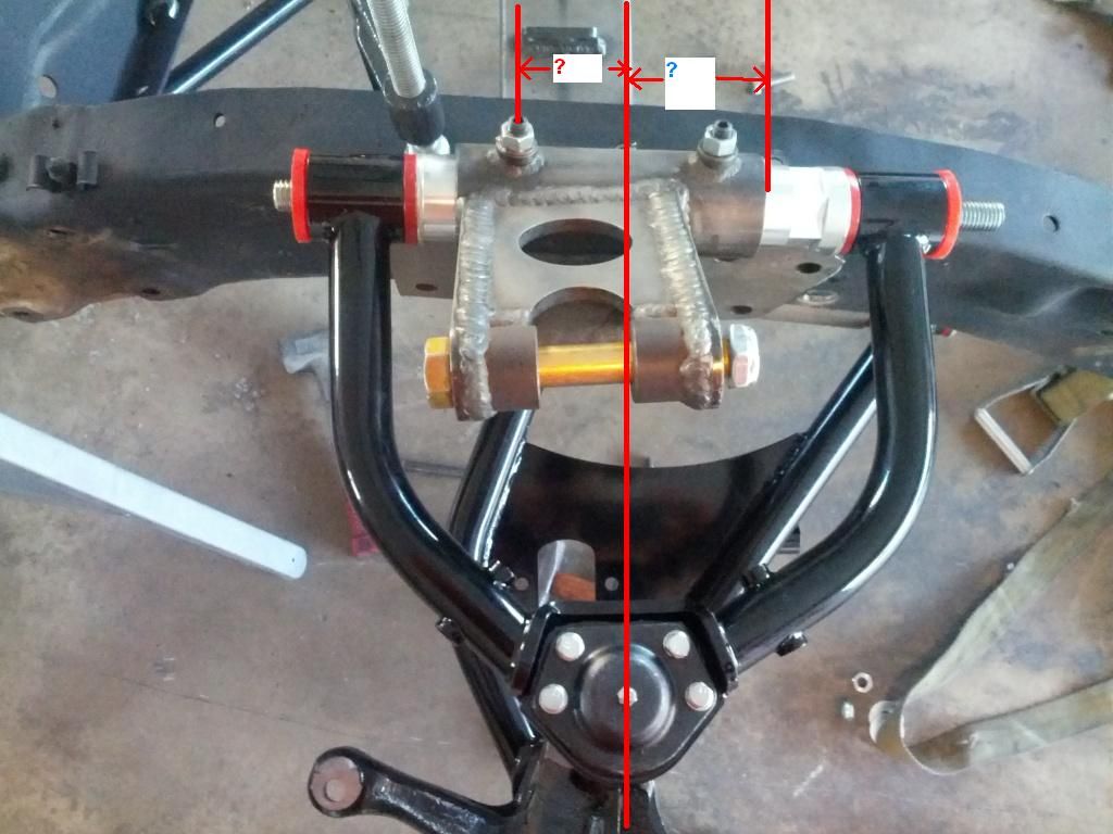 For instance if we say that the red line that passes thru the balljoint grease zerk is coincident with the axis of the spindle shaft, can you provide a measurement on the crossmember that would help locate the centerline of the axle on the frame? Assuming it's solid modeled, it should be an extremely easy number to find. 4) Does the 63-87 kit come with the stainless braide brake lines that are shown in the kit for the earlier trucks? My kit doesn't have them, and was just wondering if that's by design, or if they were left out? I hope you don't mind me posting this here instead of PMing or calling, but I figured anyone else in the future who runs into similar problems might be helped out by it. Thanks Rob, Jeff
__________________
1972 2wd K/5 Blazer Turbocharged 370 LSx - 941 rwhp / 1093 rwtq 1969 Chevy K-10 L33 5.3 / 4L80E / NP241 / 4" lift 1964 Buick Skylark Twin TURBO 383 LS pro-touring project 2014 VW Passat TDI - Daily Driver Turbo diesel 2015 Sierra Denali HD Duramax Turbo diesel 2016 Ford Explorer Sport - Twin Turbskis 2017 Polaris RZR Turbo 2014 Nor-Tech Center Console - Twin Supercharged Outboards TURBO ALL THE THINGS!! Last edited by Wasted Income; 10-11-2012 at 10:48 AM. |

|

|
|
10-11-2012, 12:51 PM
|
#2 |
|
Registered User
Join Date: Apr 2011
Location: Arizona
Posts: 249
|
Re: No Limit Wide-Ride C10 IFS 63-87
I will take some more pictures tonight and post them
|
|
|
|
|
10-11-2012, 01:24 PM
|
#3 | |
|
Boosted Member
Join Date: May 2002
Location: Mackinaw, IL
Posts: 2,200
|
Re: No Limit Wide-Ride C10 IFS 63-87
Quote:
Gump, do you know how much travel you have before there is any interference or binding?
__________________
1972 2wd K/5 Blazer Turbocharged 370 LSx - 941 rwhp / 1093 rwtq 1969 Chevy K-10 L33 5.3 / 4L80E / NP241 / 4" lift 1964 Buick Skylark Twin TURBO 383 LS pro-touring project 2014 VW Passat TDI - Daily Driver Turbo diesel 2015 Sierra Denali HD Duramax Turbo diesel 2016 Ford Explorer Sport - Twin Turbskis 2017 Polaris RZR Turbo 2014 Nor-Tech Center Console - Twin Supercharged Outboards TURBO ALL THE THINGS!! |
|
|
|
|
|
10-11-2012, 01:28 PM
|
#4 |
|
Registered User
Join Date: Apr 2011
Location: Arizona
Posts: 249
|
Re: No Limit Wide-Ride C10 IFS 63-87
I will check tonight and let you know.
|
|
|
|
|
11-23-2018, 10:48 AM
|
#5 | |
|
Registered User
Join Date: Nov 2018
Location: Guam
Posts: 4
|
Quote:
|
|
|
|
|
|
11-24-2018, 03:05 PM
|
#6 |
|
Senior Member
 Join Date: Jul 2010
Location: Dandridge, Tn. USA
Posts: 2,226
|
Re: No Limit Wide-Ride C10 IFS 63-87
1. This is the correct position of the UCA in the base configuration. This nets 3 to 6 degrees + caster. (The UCA is designed so that it can be swapped side-to-side. It can be installed with the 'short tube' forward OR the 'long tube' forward. Also, the aluminum cam can be flipped end-to-end, 'wrench flats' to the back, or to the front)
A) Short tube forward, wrench flats back, 3* to 6* +caster. B) Long tube forward, wrench flats forward, 5* to 8* + caster. C) Long tube forward, wrench flats back, 7* to 10* + caster. 2. Down travel will be limited by the coil-over, not the ball joint. "Up" travel loks limited by the port in the crossmember. I suggest using a die grinder to carefully increase the clearance for the LCA tube. Check travel with the shock installed (no spring). 3. Use the center of the main crossmember, it is 4" wide, so, 2" in from the front or back, as the new IFS C.L. 4. Brake hoses are not included with the kit. Hope this info helps.
__________________
GoodGuys 2012 Pro-Truck Champion  2012 Truckin' Throwdown Champion GoodGuys 2011 National Champion 2011 Truckin' Throwdown Champion GoodGuys 2010 National Champion Proud to put our products up against all others! |
|
|
|
|
| Bookmarks |
|
|


 Hybrid Mode
