
|
|
|
 10-15-2011, 11:30 PM
|
#1 |
|
Registered User
Join Date: Jul 2011
Location: Des Moines, Iowa
Posts: 3,016
|
Re: Project "My Happy Mess"
Me right now >
 Will post more pics tonight. Will post more pics tonight.
__________________
project: "my happy mess" |

|

|
|
11-22-2011, 02:41 AM
|
#2 |
|
Registered User
Join Date: Jul 2011
Location: Des Moines, Iowa
Posts: 3,016
|
Re: Project "My Happy Mess"
Monday Update -
Took the shroud off to paint. Scuffed with (red) scotch bright pad, air hosed off and wiped clean with lacquer thinner after. (I do for nearly everything I've painted) 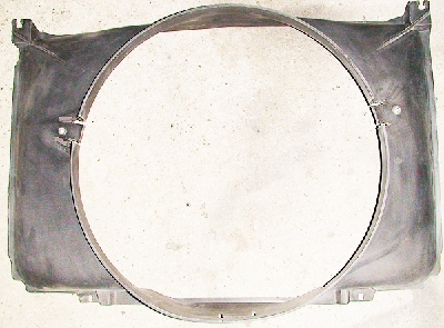 Here's the connector The Fixer used to affix the fan to the shroud. 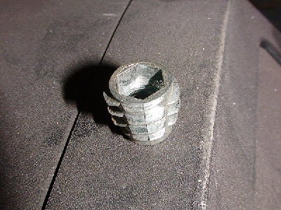 Screwed into the shroud. Plastic spacer and rubber washer. 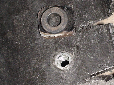 Backside - 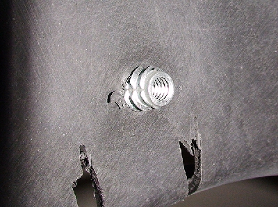 And painted. Not too happy with the paint coverage. Universal Rust-oleum Flat Black with stupid spray away nozzle. Do yourself a favor and NEVER buy this type of spray can! It was spitting blobs paint constantly. I might even redo the shroud because of it.  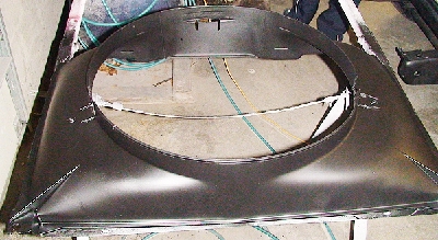 Fitted fenders, cowl and hood. The aftermarket fender fits "ok". I do not like the top/front end. Where the hood runs along side, the fender curves to the outside rather than straight or slightly to the inside like the OEM fender does on the driver's side. It doesn't look great, and I hope it doesn't mess with the grille alignment. If there's a way to get it to straighten up, I'd like to try (if at all possible within reason). No picture of that here though. I'll try and get a shot of it later. It's a Goodmark fender I think. 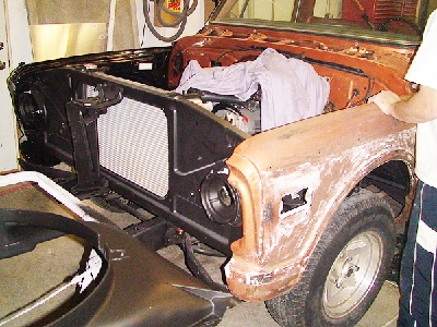  Should I keep the pinstripe work on the underside  nah nah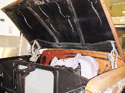 Got them "close", but still need little adjustments.
__________________
project: "my happy mess" Last edited by litew8; 11-22-2011 at 03:04 AM. |
|
|
|
|
11-23-2011, 03:11 AM
|
#3 |
|
Registered User
Join Date: Jul 2011
Location: Des Moines, Iowa
Posts: 3,016
|
Close call
Tuesday Update -
We started the day fitting the fenders, hood, rad support and grille surround. It went something like this -      My worst assumption was right on mark. The aftermarket passenger sidefender (it's a Woodall fender, I was wrong to say Goodmark earlier) didn't align worth a crap. The part I was concerned with turned out to be a big POS. The whole front of the fender pulled outward which created huge gap that wouldn't allow us to seat the grille surround, no matter what. There was no modifying this. 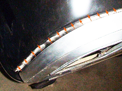 So... off it went and off we go to the body shop. I was just going to get reimbursed and get the **** out of there, but... it turned out they had a 1/2 way decent (OEM) passenger side fender. Those that know, know OEM passenger side fenders (in IA at least) are somewhat hard to come by since they are notorious for rusting out at the bottom due to battery acid and/or water damage. This one wasn't too bad, so The Fixer and I nabbed it. That damn body shop ( ) is lucky I didn't call the The Pit Boss. Here are some shots of OEM fenders and their perfect (to us) alignment!  I've got OEM grille surround, OEM fenders, OEM doors, OEM hood and OEM tailgate! Sweeet! (read Made in 1970's USA!) 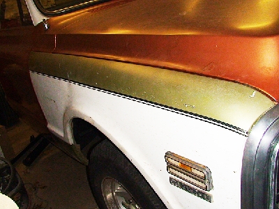 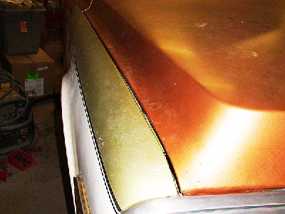  Does anybody know how long it takes to clean/sand and shine an aluminum grille surround! 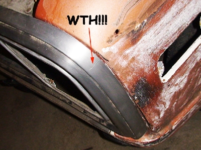 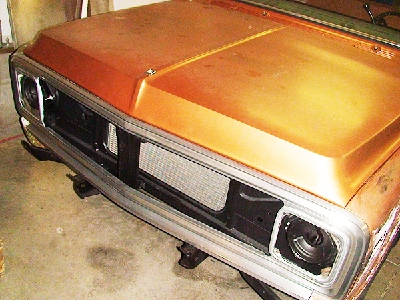
__________________
project: "my happy mess" Last edited by litew8; 11-23-2011 at 03:40 AM. |
|
|
|
|
11-24-2011, 12:55 PM
|
#4 |
|
Registered User
Join Date: Jul 2011
Location: Des Moines, Iowa
Posts: 3,016
|
Re: Project "My Happy Mess"
Thanksgiving Day Update
-Yesterday; painted some things, cut up original passneger side door and installed the grille insert (which wasn't easy!). This picture shows the aftermarket fender fitment issues before we took it back and got the OEM fender. (top view) The arrows on the right show how the fender begins to curve towards the outside, when it should do the opposite (like OEM) and curve towards the inside (engine bay). This incorrect stamping caused the rest of the front fender to mis-align and created the outer grille gap that couldn't be corrected.  Next up, cutting the old door. We're cutting a long section off of the top of the door on the old passenger side door because the new OEM replacement I have, has a large dent in it. We're just going to swap out sheet metal instead of using bondo ect... to try and fill it. There were tack welds that needed to be drilled out also. Cuts made on each end also.        When I painted the heater box, I noticed another factory marking on the inside of the box. Not sure if it's an M or W.  Painted the blower motor and touched up the shroud -   And finally, we installed the new grille insert. The odd thing here is, if we bolt down the top of the outer grill to the center brace where the hood latch is, the top of the outer grill needs pulled outward, causing the alignment to become off (not pictured here) - pulls away from the hood at an extreme. So we'll need to ream out the holes on the brace and affix the outer grill. We're not sure why this is, but just letting the outer grill sit like it wants (center) - it aligns very nice. Picture of the outer grill NOT bolted to the top center brace.  We also got the thermal switch wired. Next up, connecting the power steering return line to the pump, reinstalling the shroud and fan, some wiring for ignition and torque converter. Easy stuff.
__________________
project: "my happy mess" Last edited by litew8; 11-24-2011 at 01:07 PM. |
|
|
|
|
11-26-2011, 04:13 AM
|
#5 |
|
Registered User
Join Date: Jul 2011
Location: Des Moines, Iowa
Posts: 3,016
|
Almost there...
ty hgs
Day after Thanksgiving Day Update - Got a few more things done today. Not sure how the electric fan mod is going to react in the real world, so I reinforced it with additional grommets, washers and lock nut on the backside. If the fitting ever were to come loose (especially when I do a huge burnout in front of The Fixer's house), this mod will help ensure it stays in place. Rubber grommets on both front/back sides, against shroud. Edit: Topside pics of black headed bolt are actually old pics, they were replaced w/new, longer bolts.     Original heater core cleaned up. Was previously flushed; was clear.  Made another trip to the hardware store. Was looking for something to fill the holes on the heater box, where the lines exit. What would make a decent seal? Pipe insulation seemed like a good choice, and interestingly/surprisingly enough - it's the same color as the heater box, an exact match. I didn't want to mess with caulk or putty etc... for this. The core pressed in, the insulation smashes tight for a nice seal. Looks even better in person! Smallest piece I could find -  Gorilla tape used to hold cut pieces in place.       3M Strip-Calk used for the channel around the core area (installation not shown) -  Old/new blower motor seals. Used an adhesive to affix.     Fan relay wiring, clips I found for harnessing wires to frame, and zip ties -     P.S. Eventually I'm going to run a batch job to re-size all photos smaller.  Also, when the domain account goes away, so will all the pics.
__________________
project: "my happy mess" Last edited by litew8; 11-26-2011 at 04:42 AM. |
|
|
|
|
11-29-2011, 03:53 AM
|
#6 |
|
Registered User
Join Date: Jul 2011
Location: Des Moines, Iowa
Posts: 3,016
|
Rewiring
Saturday/Sunday/Monday Progress -
Slowly, we're getting it done. Wired up the coil the other day with what appeared to be a faulty inline ballast resistor. (You can see the (white) top of it on the other side of the power brake booster.) In part because it puffed smoke, but also because the backside wasn't sealed. We've since exchanged it and installed a new one with better characteristics.  Story time... We also needed to begin rewiring the harness to accommodate the new alternator. Ran 8awg wire, replacing the 10awg previously used. Since this SI alternator is internally regulated, we have no use/need for the factory voltage regulator (black box) that mounts to the radiator support near the horn(s) (2 horns if Custom Deluxe and up I believe). I tore off the old harness tape/wrap. It was old and brittle in a lot of places due to age. I need to replace it at some point so I decided to pick up some black electrical tape at the local hardware store. This trip turned out to be cost effective. I wanted to get electrical tape that was wide... the wider the better. The electrical dept. didn't have anything I'd like to purchase, but was told to check out another department and they may have something else. So I went to check it out. I get there and notice they have a label on the shelf that says there should be 1" electrical tape for $.80, but all that was stocked above were (3 pack) 3/4" electrical Duck tape brand for $2.80 each. I ask a representative nearby if she could check her computer systems to see if they did actually have a 1" role available in the store. She came back and said "Yes, we should have 26 roles". Hmmm, I really would like 1" wide tape. She calls the manager over and asks him. Before even looking, he says "Yes, these are them." and grabs one of the 3 pack 3/4"; I quickly correct him and pointed out that it's 3/4", not 1". Before he could get a word in edgewise, I say - "So, you'll sell me the 3 pack 3/4" for $.80 ea. (regular price is $2.80) - since you are saying it's right? (Yes, I'm taking advantage of his naivete, sue me  ) He agrees, and I again quickly say "Okay, I'll ) He agrees, and I again quickly say "Okay, I'lltake 4 packs. I'd rather have the 1" though." I grab 4 3 packs of 7milelectrical tape (12 rolls total) and head to checkout. All it cost me was $2.40 total. Plenty enough to re-tape all my wires, and have lots left over for future use.  Some pictures of cleaning up the wires. Made a quick illustration of how (I think) the rewiring is suppose to be to accommodate the new SI alternator (internal regulator).   The cluster of wires wrapped to the left in the above picture is where the factory "junction" is. This is where everything ties in together and power is distributed (to cab, lights, horns, etc...).  Mine is a 3 wire setup, not 1 wire. Although the alternator can wire either way. Ran 8awg from the alternator BAT terminal to the "junction". Ran 8awg from the "junction" to the Battery (aka Charge wire - it runs up and along the loom on top of the radiator support next to the radiator). The above is fairly new to me, please correct me if I've missed a step or if something isn't right! The F/L are still connected at the alternator as it was factory. I read it is important to retain the "Remote Field sensing" wire to the "junction" for a more accurate reading rather than jumping the wire to the BAT terminal on the alternator. Pics for the Pit Boss. This is a picture puzzle for him to figure out.  
__________________
project: "my happy mess" Last edited by litew8; 11-29-2011 at 04:11 AM. |
|
|
|
|
11-29-2011, 04:54 PM
|
#7 |
|
Registered User
Join Date: Jul 2011
Location: Des Moines, Iowa
Posts: 3,016
|
Details
Getting really close now!
The Fixer had some wrap, so instead of using electrical tape to wrap all the wires, I went with his stuff. He said it was used to wrap industrial underground water pipe. It resembles the factory wrap a lot. It is stretchy and doesn't have adhesive, but it does bond to itself nicely.   Got some (free) electrical conductive grease to put on contacts, etc... This will prevent corrosion from forming and maintain good connections. I used it on everything. Connectors to the cab, light plugs, spark plugs, distributor, coil, battery, alternator, etc... Anything that has an electrical current and susceptible to elements. Reading material More material       
__________________
project: "my happy mess" |
|
|
|
|
11-30-2011, 05:48 AM
|
#8 |
|
Registered User
Join Date: Jul 2011
Location: Des Moines, Iowa
Posts: 3,016
|
Re: Project "My Happy Mess"
The above wiring diagram isn't correct.
Here are some revised pictures of the wiring, with hopefully better detail. Keep in mind, this is for a 3 wire configuration, not 1 wire.    
__________________
project: "my happy mess" |
|
|
|
|
12-02-2011, 04:23 PM
|
#9 |
|
Registered User
Join Date: Jul 2011
Location: Des Moines, Iowa
Posts: 3,016
|
Re: Project "My Happy Mess"
More problems sponsored by, "My Happy Mess"
We realized that the detent (kickdown) cable on the transmission was broken near the base. Maybe it hit the firewall just right when we installed the engine and transmission. We can't have this piece busted since it helps regulate downshifting when I put the pedal to the metal. I order a different cable that came with a mounting bracket for the manifold. It's a Lokar kit (KD-2350U). First thing we realize after receiving it is that the mounting bracket doesn't align correctly with rear intake manifold bolt holes. So we pulled the bracket apart to adjust the distance between the two, and it worked. Next thing we notice is that there's no way the bracket is going to clear the valve cover. The bracket is angled too much and it'd hit. I called Summit tech line and questioned the kit's fitment. I can tell all he did was look it up on the internet and couldn't provide any real insight. He says I didn't have all the necessary brackets. I say it came with it, and he mentions there's another bracket that is a "related" item for it. YEAH, riiiight, I'm going to buy ANOTHER bracket.  So... more modifications are necessary. Here's how the bracket would have sat on the manifold -  Modified - We simply hammered down the tabs to near 90 degree angles so that it'd sit on the manifold at a more upright position, clearing the valve cover. I used a towel and hammer. The towel prevented scratching the finish.   And this is how it ended up on the manifold   Other - Painted the timing mark white on the harmonic balancer. Notice the issue here? Since the timing chain cover is aluminum, it seems it's a slightly thicker casting (remember the fitment issue with the water pump?) The timing marker sits out too far when mounted, and almost covers the entire surface end of the harmonic balancer, nearly concealing the timing line. To help visually see the line when we shoot it with a timing gun, I painted the line white.  ----- We tested electricity little more today too. The fan works good! (never really did before) Since there's a lever busted on the backside of the controler, I have to manually open or close the door inside of the heater box by hand, inside of the cab. It's easy to reach. I think the only downside to keeping it open (full air flow) is that it will draw in too much air when it's cold. The opening of the flap/door in the heater box regulates with the fan speed. The door is slightly opened when the fan is switched to low speed, opens more with med. speed and opens fully when the fan is set on high speed. Previously I found a tear in the defrost vent tube next to the oil pressure line when I installed the instrument cluster. I taped it up by wrapping a few times with Gorilla tape. Sealed it nice. Now I've got full air to the defrost. ----- Since I don't have a horn button, we used a screwdriver on the steering wheel to jump it. We could hear the horn relay kickin under the dash by the fuse box, but no horns. 
__________________
project: "my happy mess" Last edited by litew8; 12-02-2011 at 04:32 PM. |
|
|
|
|
12-07-2011, 03:01 AM
|
#10 |
|
Registered User
Join Date: Jul 2011
Location: Des Moines, Iowa
Posts: 3,016
|
Re: Project "My Happy Mess"
Thanks ChevyMan.
 Here's a few misc. pics of the fuse holders I bought to replace the old ones with (I've since soldered them on both L/R sides) and the transmission detent (kickdown) cable (in case some don't know it). New (4A mini fuses) -   Old (4A fuses) -   Transmission detent (kickdown) cable next to dipstick -  Extra - Another "picture puzzle" for The Pit Boss to figure out.    Thanks for looking all. Hopefully more progress soon. It is DAMN COLD here! We're working out of a heated garage, but the cold zaps my energy.
__________________
project: "my happy mess" |
|
|
|
|
12-07-2011, 03:26 AM
|
#11 |
|
Registered User
Join Date: Jul 2011
Location: Des Moines, Iowa
Posts: 3,016
|
Re: Project "My Happy Mess"
Edelbrock power graph
 Edelbrock top end kit dyno matched to produce. Though take into consideration exhaust etc... Before I once said I wanted "to go fast!", clarified - I want to go fast off the line up to driving speed. I'm not a speed freak. 
__________________
project: "my happy mess" |
|
|
|
|
12-08-2011, 06:45 AM
|
#12 |
|
Registered User
Join Date: Mar 2010
Location: Forest Hill, MD
Posts: 171
|
Re: Project "My Happy Mess"
Really enjoyed your build thread. Very very nice work!!! Got some good ideas from you for my current 72 K20 rebuild. Love your detail.
I saw that you found number 441 in a lot of places. On my 72 I found the number 329 handwritten in quite a few places (firewall, behind dash, gas tank behind seat, top of transmission bell housing, stamped into top edge of firewall above brake booster). I went ahead and hand wrote the number again on the parts after they were painted. Maybe one day we'll hear from someone that worked at a GM plant and give us some history on those numbers. Looking forward to your future posts.
__________________
72Kay20 Bel Air, MD 1972 Hugger Orange K20 LWB 350, 4wd, 4spd Sm465, Dana 44, HO52 Other Toys 69 Cortez Silver Z28 86 White Buick T Type |
|
|
|
|
12-09-2011, 12:41 PM
|
#13 |
|
Registered User
Join Date: Jul 2011
Location: Des Moines, Iowa
Posts: 3,016
|
Re: Project "My Happy Mess"
Thank you for the kind words 72KAY20, glad you are finding some info useful.
The bad news is, we're not going to be able to paint this winter.  Too cold and our ventilation system sucks too much hot air out of the garage. The good news is, maybe we'll try and fire it up today! Here are some more pics for The Pit Boss. No puzzle.    
__________________
project: "my happy mess" |
|
|
|
|
12-09-2011, 04:13 PM
|
#14 |
|
Registered User
Join Date: Jul 2011
Location: Des Moines, Iowa
Posts: 3,016
|
Re: Project "My Happy Mess"
Well, that didn't work! After all that work, turns out the base of the transmission dipstick tube has a hairline crack in the base and transmission fluid was seeping out after 2qt. The fluid must have been coming from running down the tube on the inside, since 2qt isn't enough to reach the base of the tube from the bottom up. Went and bought another dipstick/tube and will install later. Oh well.
__________________
project: "my happy mess" |
|
|
|
|
12-16-2011, 01:00 PM
|
#15 |
|
Registered User
Join Date: Jul 2011
Location: Des Moines, Iowa
Posts: 3,016
|
Re: Project "My Happy Mess"
For those that are still looking, I'm still here. Haven't fired it yet. Christmas time and all. Update on the horns - we wired them directly. Of the two, one didn't sound at all, the other did... for a while, until it too burned up.
Now there are none. 
__________________
project: "my happy mess" |
|
|
|
|
12-20-2011, 02:58 AM
|
#16 |
|
Registered User
Join Date: Jul 2011
Location: Des Moines, Iowa
Posts: 3,016
|
Re: Project "My Happy Mess"
hgs, I'll send you a PM.
----- Christmas week update. Probably won't get much done the rest of this week. But I'll post what I could find, and what I did the last few days. Found a pic I hadn't posted early on. The aluminum cam button we used. Machined by a local. Yeah, I'm cheap.   Decided to go ahead and rewire the electric fan with a plug. Took a trip to the junkyard the other day. It was nice and muddy, from the rain the day before. Yay. They only had two Jeep's, completely stripped. No plug. On my way out I was looking desperately for anything that would work. I needed the right sized AWG to match up with the fan/relay wires. The only other requirement - it needed to be a two wire connector (+,-). Sorry all, but I found a nice sized connector off a *ord. While walking by,I seen one end sitting there. I thought to myself, the other end has to be nearby! Sure enough , it was on the other side of the enginebay. I quickly ripped out the wire holders and cheap loom, cut the wires with enough to spare - and was on my way. 2 bucks. Not bad ,considering all the local stores couldn't produce. Had some shrink tube large enough to cover the ends, so I figured why not? (I'll never need to use this large of shrink tube for anything else (was part of a kit)).     Shrink tube - will reduce to 1/2 it's size, using a mini torch or heat gun.   Shrunk -   Next, I soldered one end to the fan. Before soldering, I put two small pieces of shrink tube on each wire. Far enough away from the heat of the mini torch I used for soldering - so that the tubes don't shrink from the heat.  Sorry, didn't have time to get a manicure.    Pulled the fan's plastic sheathing up and over as much as I could. I'll just tape up the rest. Not too concerned with it. I'll put some conductive grease inside there too, after I finish soldering the other end.  Lastly, the Woodsmith dropped off bed wood.  
__________________
project: "my happy mess" Last edited by litew8; 12-20-2011 at 03:16 AM. |
|
|
|
|
12-26-2011, 12:16 AM
|
#17 |
|
Registered User
Join Date: Jul 2011
Location: Des Moines, Iowa
Posts: 3,016
|
Re: Project "My Happy Mess"
My VIN numbers (cab & frame) are verified/match. C20 (3/4). 21+ years ago someone converted it to a C10. Whoever did it, did an awesome job. Made my clean up/restoration job a lot nicer.
Another shop light  Sign/clock in the shape of a muffler A gift for The Fixer. This is a one of a kind find (made in 93'). 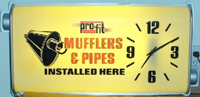 Not yellow in person, it's white. The wall in the background is white also. Not sure what the deal is. Prob. the cheap "green" bulb in the kitchen.
__________________
project: "my happy mess" Last edited by litew8; 12-26-2011 at 12:24 AM. |
|
|
|
|
12-26-2011, 01:38 AM
|
#18 |
|
Registered User
 Join Date: Apr 2008
Location: San Diego California
Posts: 1,316
|
Re: Project "My Happy Mess"
Mine had the heavy duty Dana 60 with the leaf springs, the carrier bearing is also the heavier duty one. I found this out when I had my new drive shaft made and researched the bearings.
Maybe since yours was the 3/4 ton with trailing arms they thought they needed the extra braces. I'm going to be shortening the drive shaft because the 700r4 is a different length so I will be upgrading that bearing. I bought my truck from the original owner who bought it at the dealership about three miles from my house. It's history is all right here in San Diego, cab and frame are all original It did not look like your sand blaster shielded much when he was blasting, Are you going to replace your U-joint? probably full of grit.
__________________
I'd rather attempt something great and fail.. than try something ordinary and succeed. Norman Vincent Peale Project: Barn Raising http://67-72chevytrucks.com/vboard/s...d.php?t=414961 Project: 30 Be Low https://67-72chevytrucks.com/vboard/...d.php?t=830583 Last edited by Mike Bradbury; 12-26-2011 at 01:45 AM. |
|
|
|
|
12-29-2011, 04:52 AM
|
#19 |
|
Registered User
Join Date: Jul 2011
Location: Des Moines, Iowa
Posts: 3,016
|
First Fire Videos
First Fire 12-28-2011Small clips. Dubbed using my old camera via HD camcorder >> TV I'll have some more videos later. Sound quality isn't all that great. Full exhaust (glass-packs). For sure I'll need mufflers. First thing to check! WTH!
Oil pressure is off the chart! (good thing at least) May need to call it in as defective. 0 leaks Part 1 Part 2 Part 3
__________________
project: "my happy mess" Last edited by litew8; 12-29-2011 at 05:08 AM. |
|
|
|
|
01-01-2012, 02:36 PM
|
#20 |
|
Registered User
Join Date: Jul 2011
Location: Des Moines, Iowa
Posts: 3,016
|
Re: Project "My Happy Mess"
Previously - how the transmission dipstick tube/detent cable turned out -
Took the instrument cluster out and removed the oil pressure gauge - Oil pressure gauge comparison. Old/top, New inaccurate/bottom - Look at the quality of the old gauge. Amazing - much better. Haven't messed with the gauge yet. Not sure if the needle can be moved on it's own or not. Also not sure if that wire on the bottom is suppose to have a bend in it or not.
__________________
project: "my happy mess" |
|
|
|
|
01-01-2012, 03:30 PM
|
#21 |
|
Registered User
Join Date: Jul 2011
Location: Des Moines, Iowa
Posts: 3,016
|
More Videos
These clips didn't make the cut earlier.
The 1991 PO had Dynomax mufflers installed (with headers).  Great choice. The Pit Boss had Walker mufflers on his Mustang too. After looking around, I think Dynomax (Walker) Hemi Super Turbo mufflers will quite my exhaust to what I'm looking for, if we can fit them. Loud only on demand. I've read these are a little louder than OEM, but considering my engine is a little more than OEM ( ), should be a good fit for thesound I'm looking for, at a good price. 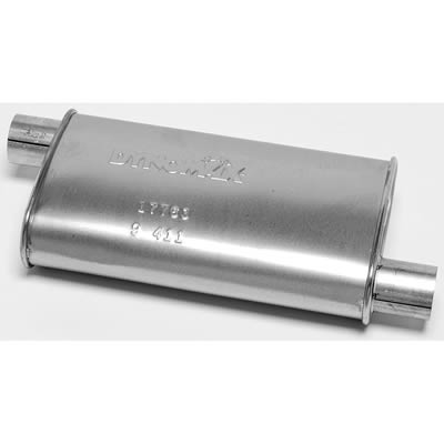 There's also Walker Quiet Flow 3's in considreation - 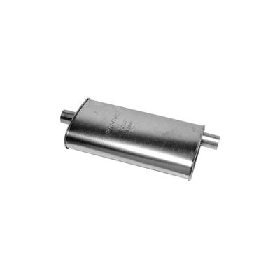 Either one should quiet/tone down this :
__________________
project: "my happy mess" Last edited by litew8; 01-01-2012 at 03:45 PM. |
|
|
|
|
01-02-2012, 12:09 PM
|
#22 |
|
Registered User
Join Date: Apr 2008
Location: San Diego California
Posts: 1,316
|
Re: Project "My Happy Mess"
I don't know how much you want to/ or feel comfortable with "fixing" the new inaccurate gage. If it were me I would just look for a better quality one rather than risking torching my new engine because of a faulty gage. It is cheap insurance.
__________________
I'd rather attempt something great and fail.. than try something ordinary and succeed. Norman Vincent Peale Project: Barn Raising http://67-72chevytrucks.com/vboard/s...d.php?t=414961 Project: 30 Be Low https://67-72chevytrucks.com/vboard/...d.php?t=830583 |
|
|
|
|
01-02-2012, 04:21 PM
|
#23 |
|
Registered User
Join Date: Jul 2011
Location: Des Moines, Iowa
Posts: 3,016
|
Re: Project "My Happy Mess"
I managed to move the needle down to L on the gauge. I didn't want to bend the wire affixed to the needle, risking messing up the proper contour/alignment of its function. I held the element firm and turned the needle. Reinstalled the cluster. We'll see how it goes. Spent prob. 1/2 hour on it. Not sure what 20/25% more volume will do to the gauge, hopefully it's finished expanding and will provide an adequate reading. We're going to install an external gauge to measure pressure for certainty, eventually. We'll test the oil pressure gauge mod. and temperature gauge tomorrow.
New oil pressure gauge, needle relocated -
__________________
project: "my happy mess" |
|
|
|
|
02-20-2012, 04:17 PM
|
#24 |
|
Registered User
Join Date: Jul 2011
Location: Des Moines, Iowa
Posts: 3,016
|
Monday Update: Starting interior
Here are the two OEM cigar lighters I bought. I made one good one out of two.
The face on one was pitting bad, so I used parts from it to use on the good one. Before:  After (I've never had this cigar lighter during ownership).Sand blasted and painted. Polished aluminum (?) button was masked off.    Found another color code. This time on the gas tank, 441:  Pictures of parts being sand blasted (in our new blast cabinet) and painted (ZR):      Some "how it was done" shots, before and after: Before:            After:      No more "windows being jacked up, rolling up/down"! All my original door guts are now NOS! --------------------- Next up, I tackled the cab floor. Installed Hushmat and placed the jute pad and rubber mat. We'll be repairing pass. door (top/inside), assembling the doors guts, painting door jams and kick panels next. Before installing the Hushmat, I wanted to prep (clean) the surface some. I blew it clean with air hose, then wiped it down with degreaser. After, I spot sprayed areas with ZR just for peace of mind.   Not really necessary, but I used a paint pen to mark where holes are beneath.      Turned out sweet! Turned out sweet!Considering going to the local auto store and have them match/mix up some sandalwood paint in an aresol can - to paint the rubber floor mat to match the dash pad and steering column. My old mat is a light beige (factory Color Keyed mat). Then I'll probably put another (different size/black) mat on top of this one for better protection. ------------- Picture puzzle for the Pit Boss. Name this area.   
__________________
project: "my happy mess" Last edited by litew8; 02-20-2012 at 04:27 PM. |
|
|
|
|
02-21-2012, 04:45 PM
|
#25 |
|
Registered User
Join Date: Jul 2011
Location: Des Moines, Iowa
Posts: 3,016
|
Re: Project "My Happy Mess"
Took my old rubber mat to the car wash. De-greased with the tire spray then soap/water to rinse. Aside from the two tears on the inner corners, it still looks great! For sure they don't make this style/quality any longer (I've looked). This is the rubber mat that will lay on top of the rubber floor cover.
Went to the auto store and took a chunk of the old rubber floor cover to try and match paint. Might be hard to do since the good colored portions are small and not so flat. They'll figure something out, and we'll shoot it with a gun instead of it being in spray cans. The black mat below will sit on top, so I'll end up having Sandalwood (bottom/outline) with black on top. Full floor mat with Chevy truck on it! How COOL is that!!   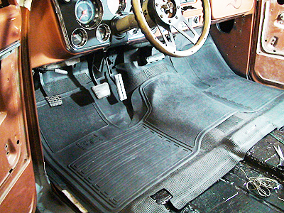 Also, today I stuck the door panels into the blasting cabinet and shot both sides! Painted the metal back w/ZR and I'll paint the front w/fresh white.  
__________________
project: "my happy mess" Last edited by litew8; 02-21-2012 at 04:52 PM. |
|
|
|
 |
| Bookmarks |
|
|


 Hybrid Mode
