
|
 07-28-2021, 08:35 AM
|
#126 |
|
Registered User
Join Date: May 2009
Location: Grey County Ontario
Posts: 205
|
Re: Project Fargolet
Edgeleycanuck: Those suggestions were not helpless! As for the suv/mini van wipers I believe they are not a great fit for my header panel, and they tend to have a big sweep (like 120 degrees). I did end up looking at both tractor and marine wipers (with success-see below!).
6DoF: Thats an option that I was reserving for later, in case I couldnt find a matching pair with 90 degree sweeps. My previous efforts to take apart electric motors have generally resulted in an explosion of tiny springs and magnets and stuff, so I was leery of opening a new motor up! Heres what I finally did in order to get a pair of good, strong, reliable wipers. This truck will not see rain often, but my area is very hilly so I really wanted to go electric. After an absolute ton of internet searches and unanswered emails from tech support at a couple of suppliers, I ordered a wiper designed for a tractor. I knew it was going to be bigger than I wanted, but I am happy with what I got. I bought a Case-IH VLC3005 motor that has a toggle switch built in. It does protrude into the cab from the header panel, but thats where the toggle switch is, and in an old truck with utilitarian features, the protrusion really isnt out of place. This motor is the same as all the other universals, as it has 2 shafts that go through the roof skin above the windshield. There is a round, solid inner shaft that the wiper arm attaches to, and a threaded outer shaft that is used to secure the wiper to the roof skin. If the shafts are too long, you simply cut off whatever is not needed. Heres the new motor, with the excess shaft lengths already cut off:  These little universal motors mount by tightening 2 nuts that firmly clamp the threaded shaft to the roof skin (one nut inside the roof skin, one nut outside the roof skin). They also have a small tab that needs to get affixed to the body in order to keep the motor from rotating due to the twisting force of the wiper. Due to an inner sheet metal lip where 2 roof panels met inside, I needed to create a spacer that would set the motor about 2 inches inside of the roof skin. I was scratching my head over how to create a metal bracket to do this, when it occurred to me that I am not limited to metal. These trucks used a fair amount of wood in their construction (even the cab used to sit on wooden blocks), so I grabbed a piece of wood, took a few measurements, made a quick guess or two, and then used a chop saw to make spacer version 1.0. Its murder getting inside that header panel to take accurate measurements, so version 1.0 was meant to just be a test piece. Imagine my surprise when I installed it and it fit perfectly! Using a spacer block was also very useful, as it allowed me to tighten the motor in place using only one nut from the outside of the roofskin (there is no access whatsoever to be able to get a wrench onto a nut on the inner skin, which is how these are meant to be attached). Here is the new motor, with spacer 1.0 in place:  Next came the outer fitting. The wiper shaft protrudes through the roof skin at about a 70 degree angle, so I needed a 70 degree fitting to clamp the wiper in place. This was just a matter of grabbing a piece of solid round bar, drilling a hole down the centre of its axis, and then cutting off a piece at the correct length and angles (90 degree at one end, 70 degree at the other). 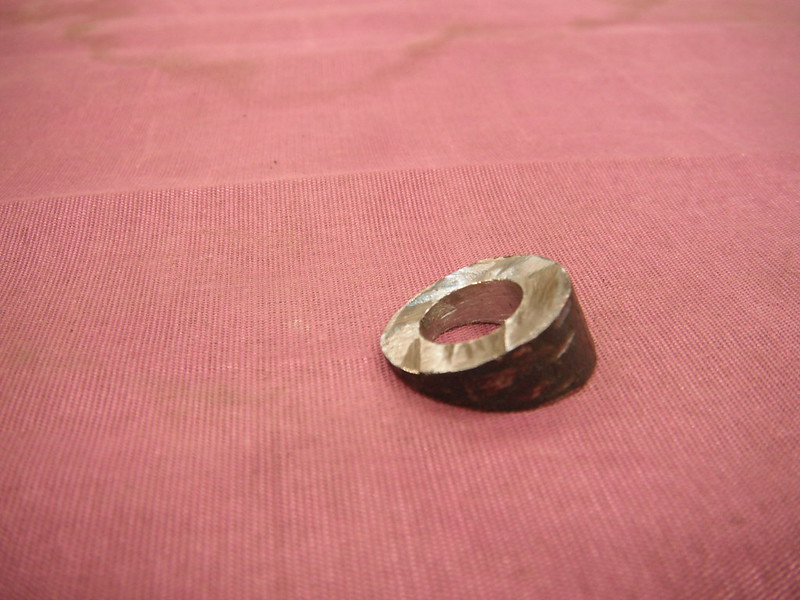 I then cut up a couple of seals to keep water out and bolted the whole mess together. Heres the outside now:  Next came the anti-rotation tab. For this I just fabbed a little tab that attaches to the windshield hinge bracket on the driver side.  For the passenger side it got a little trickier as the anti-rotation tab is not on the same side as the windshield hinge bracket. I made this little attachment tab which will be temporarily bolted into place against the header panel. Once I know that everything is good, I will remove the bolts and weld it in place permanently.  The wooden spacer for the passenger side was identical, so making a 2nd one was 5 minutes work. Heres the driver side with the motor in place. I still need to fab up a panel that covers the access hole and trims up the motor to make it look more like its supposed to be that way (remember it protrudes into the cab a bit).  Next came the wiper arms and blades. Aside from using stock ones, there appear to be 2 common styles of universal aftermarket alternatives. There are the arm & blade combos that seem to come with all the aftermarket universal wiper motor kits (the lower combination in the photo below), or I could use the Anco 41-01 arm and the Trico Classic blade (upper combo in this pic):  For those who are interested, Ill share some comments about these 2 wiper combo choices. Anco/Trico combo: -$43 Cdn at Rockauto for one arm/blade set -Arm length is adjustable -Blade angle is adjustable -Construction is very strong (thick metal, well made) -Spring inside arm is very strong (likely too strong for vacuum wipers, but can be adjusted with some tinkering as I did on page 4 of this build thread) -Arm comes with adapters to fit most common wiper posts -Dull metallic silver finish on arm, chrome on blade frame Universal kit combo: -$20 Cdn per set at various online vendors in the US -Arm length is adjustable (but the construction makes it a bit tough to do at points) -Construction is horrible (poorly stamped, thin metal, flimsy and overall awful) -Spring is moderately strong -Blade can be shortened by cutting it (useful for minor interference with windshield frame) -Blade angle not adjustable -Arm comes with adapters for 2 different post types -Chrome finish on both arm and blade I went with the Anco/Trico combo, but both would work on the Fargo. Here is a pic of the driver side. It just needs some adjustment to optimize the swept area, and I need to lower the blade a bit by adjusting the arm length (super simple to do).  I hope I wasnt too long winded about installing wipers, but I have to say that getting these things sorted out was actually one of the trickies jobs Ive had on this swap! |

|

|
|
07-28-2021, 02:04 PM
|
#127 |
|
Registered User
Join Date: Sep 2019
Location: Maynooth, Ontario, Canada
Posts: 174
|
Re: Project Fargolet
Tooo long...not by a long shot. The more info given the better chance of Borrowing your information and getting it right. Thanks for taking the time to tell us this.....Your truck is coming along nicely.
__________________
http://67-72chevytrucks.com/vboard/s...82#post8619382 |
|
|
|
|
07-29-2021, 11:16 AM
|
#128 |
|
Registered User
Join Date: Sep 2018
Location: Ontario
Posts: 788
|
Re: Project Fargolet
I always enjoy your posts and learning how you 'overcome' each task.
Thank you for taking the time to post pics and describe each project. This is going to be a very well built and cool truck when it's done. (can't wait to see it) another task completed, .... on to the next one
__________________
https://67-72chevytrucks.com/vboard/...=797726&page=3http://https://67-72chevytrucks.com/...=797726&page=3 51 Chev 5 window on S10 with SBC 1958 Pontiac Wagon build https://67-72chevytrucks.com/vboard/...d.php?t=849781 |
|
|
|
|
08-13-2021, 07:00 AM
|
#129 |
|
Registered User
Join Date: May 2009
Location: Grey County Ontario
Posts: 205
|
Re: Project Fargolet
Thanks guys! I always hope that detailed instructions may help someone else avoid having to reinvent the wheel (god knows I have borrowed enough ideas from others in this build). While waiting for those darn door latch mechanisms to come back in stock I have kept busy with some minor things on the truck. First was the headlight buckets.
While reassembling the front end I realized that one of the headlight buckets was canted upwards. These fenders had been horribly bashed and I did my best to remove the biggest dents, however the area where the headlight buckets mount did not come out as well as I had hoped. I could have taken it all apart and started bashing again, but I am lazy so I did something simpler. Here is the headlight bucket that points too far upwards: 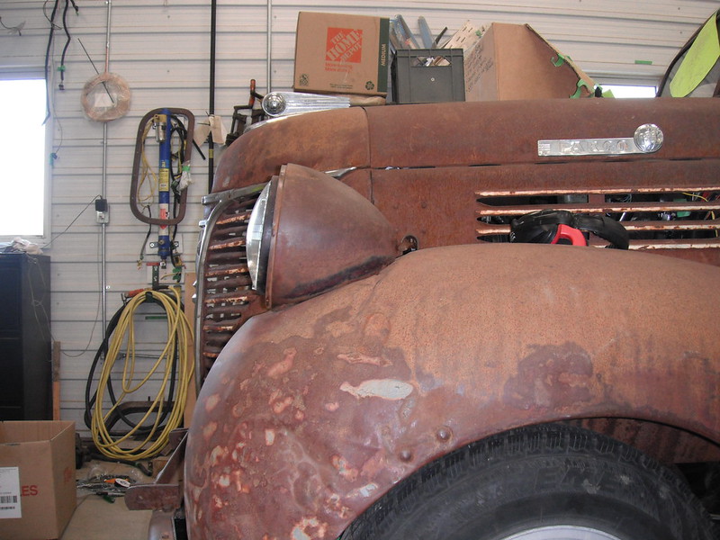 These buckets sit on a thin rubber pad (which I didnt have anyhow), so I grabbed a thick piece of rubber and made a pad, then hit it with a die grinder to adjust the way the bucket sits:  Once that tapered pad was installed, the bucket pointed forward:  Next I decided to try something different with the S10 gauges. My first attempt (Version1.0) was far from satisfactory. The needles sat deep in the housing, and I had completely forgotten about the fact that my seating position results in me looking down, rather than straight at the gauges. As a result, the needles and markings were half hidden from my sightline. I was going to just redo them, bringing the needles forward, but I realized that if I do that I will lose the light that lets me see them in the dark. I seemed to be stuck, but then realized I could use the original S10 gauge faces. Yeah, its not gonna look period correct, but then neither does the speedo. It was time to stop dithering and make something I could clearly see during both day and night. Heres what I did. I cut a piece of ⅜ plexiglass to fit inside the housing: 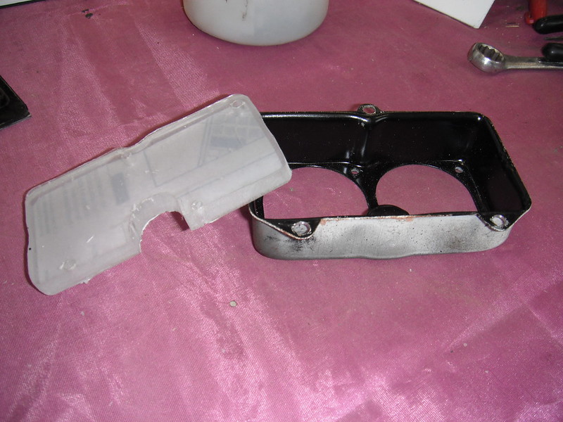 The S10 gauge face is a thin sheet of plastic which is glued to a clear panel in the instrument panel. I have no idea what kind of glue GM uses, but it is amazing. It's super hard to pull that face off, however once its off the glue is still there, and is still SUPER sticky (even after 25 years). I cut out the face sections around the gauges and stuck them onto the piece of 3/8ths plexiglass: 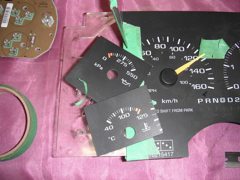  I gave it a test tug and that glue would not let go. Wow! I finished drilling all the holes I needed, popped the needles onto the gauges and then made fresh front borders. I now needed light. The S10 gauges are designed to let light in from the rear, so I fabbed up a couple of brackets that would hold a light behind each gauge set:  I put it all together and heres how it looks now:  The gauges are far easier to see now. I am still not thrilled about the modern look, but they are functional, and will work for now. My goal at this point was to use everything I could from the donour vehicle in order to get this truck onto the road with minimal costs (version 2.0 cost me about 5 bucks to do!). I have a list of future mini projects, and I think I will add nicer gauges to that list. I got a bit stubborn trying to prove to myself that the S10 gauges are reusable. While I finally did do it, the ordeal reminded me of the expression just because you can, doesnt mean you should! |
|
|
|
|
08-16-2021, 07:18 PM
|
#130 |
|
Registered User
 Join Date: Feb 2020
Location: Boulder, CO
Posts: 221
|
Re: Project Fargolet
I like the gauge work. A lot of time and effort there but it looks good. Excellent work.
|
|
|
|
|
08-17-2021, 04:38 PM
|
#131 |
|
Registered User
Join Date: Sep 2019
Location: Maynooth, Ontario, Canada
Posts: 174
|
Re: Project Fargolet
Nice work as usual
__________________
http://67-72chevytrucks.com/vboard/s...82#post8619382 |
|
|
|
|
08-23-2021, 04:36 PM
|
#132 |
|
Registered User
Join Date: Sep 2018
Location: Ontario
Posts: 788
|
Re: Project Fargolet
maybe some 'antique' white needles will help it look more vintage..... I think it helped mine
The gauges look really good in the original housings, I hope they work for you
__________________
https://67-72chevytrucks.com/vboard/...=797726&page=3http://https://67-72chevytrucks.com/...=797726&page=3 51 Chev 5 window on S10 with SBC 1958 Pontiac Wagon build https://67-72chevytrucks.com/vboard/...d.php?t=849781 |
|
|
|
|
08-28-2021, 07:08 AM
|
#133 |
|
Registered User
Join Date: May 2009
Location: Grey County Ontario
Posts: 205
|
Re: Project Fargolet
Thanks guys, and Tempest67 I may give that a shot ( I have extra gauges in my parts truck). It made a big difference in your gauges. I would have to figure out how to open up the speedo though, and it appears crimped together (not meant to be openable) so I have to see if I can open it without wrecking it. For now I know they work, and I can see these ones far better than version 1.0 so Im good to go!
While doing the gauges and other dash work, I had been taking advantage of the giant hole that had been cut into the dash by a previous owner. The hole seems to be the result of the removal of the windshield lift system, and that hole was actually convenient as it allowed me to comfortably reach behind the dash to instal stuff. What wasnt convenient was having no lift mechanism, and having to patch that intricately shaped piece of missing metal. I had made the patch and lift system earlier, so it was time to finish things up. Here is the lift system that I whipped up: 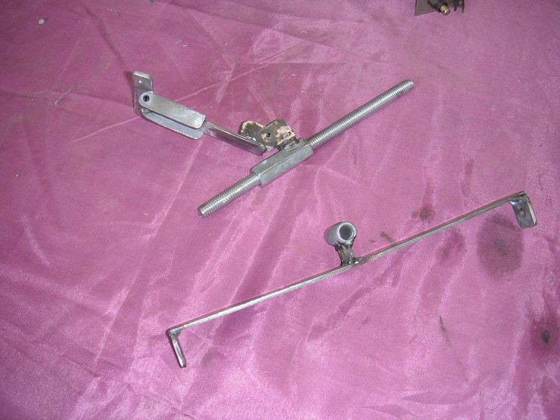  Its really nothing more than a coupling nut that runs on a 3/8ths threaded rod. By spinning the rod, the nut can move back & forth, pushing or pulling the double hinged assembly that attaches to the base of the windshield. The entire mess gets supported by the dash on one end, and by that wide lower bracket that bolts to the cowl vent assembly:   The last thing to do was to shorten that threaded rod to final length and add a handle of some sort. My neighbour gave me a leftover handle from his Model A build, which I cut and welded to the threaded rod (adding a small collar and washer to make it look spiffy). I can install the entire threaded rod assembly by sliding it through the dash hole and threading it in until it bottoms out in the cowl vent support tube, a simple washer and cotter pin then secures it to the inner face of the dash (very easy to do as access is good at that spot from underneath):  And here she sits. I still need to final weld and finish the patch, but this was strong enough for test purposes. I was pleasantly surprised to find that I could easily raise or lower that heavy windshield by spinning the handle with just one finger. Its not fast, but the power of the inclined plane is an amazing thing!   I made one tactical error here by putting my welds on the top side of the bracket, close to where it attaches to the windshield base, so they are visible and kinda ugly. Ill fix that later when I do dash bodywork. More to follow! |
|
|
|
|
08-28-2021, 02:36 PM
|
#135 |
|
Post Whore
Join Date: Aug 2014
Location: Sacramento, CA
Posts: 10,803
|
Re: Project Fargolet
s!ck Fab Skillz
|
|
|
|
|
08-28-2021, 02:38 PM
|
#136 |
|
Senior Member
Join Date: Sep 2017
Location: Bryan, Texas
Posts: 2,265
|
Re: Project Fargolet
Amen!
__________________
8man-aka Robert 1948 on a S10 Frame, small block with a carb 1954 Cab, 53 Front and Bed, 50 Doors, S10 Frame, Power TBD Build thread: "]http://67-72chevytrucks.com/vboard/showthread.php?t=746899&highlight=wife%27s+48[/URL] [/URL]http://67-72chevytrucks.com/vboard/showthread.php?t=840204 |
|
|
|
|
08-28-2021, 10:26 PM
|
#137 |
|
Senior Member
Join Date: Aug 2010
Location: Shasta Lake, CA.
Posts: 1,619
|
Re: Project Fargolet
Now that’s cool … lol
__________________
Glen & Jane's Rides 57 GMC NAPCO Long Bed V8 4 speed Bought 2008 7 other cars & trucks , 5 trailers '56 Chevy Long Bed I6, 4 speed Bought 1990 Sold 8.22.2020 56 GMC Suburban Pickup V8, 4 speed Hydramatic Bought 1996 Sold 10.11.2020 My Other Tinkerings http://67-72chevytrucks.com/vboard/s...75#post8967275 |
|
|
|
|
08-30-2021, 07:54 AM
|
#138 |
|
Registered User
Join Date: Nov 2014
Location: somewhere, PA
Posts: 1,021
|
Re: Project Fargolet
so many great little details!
|
|
|
|
|
08-30-2021, 10:06 AM
|
#139 |
|
Registered User
Join Date: Sep 2018
Location: Ontario
Posts: 788
|
Re: Project Fargolet
What great problem solving, thanks for sharing.
__________________
https://67-72chevytrucks.com/vboard/...=797726&page=3http://https://67-72chevytrucks.com/...=797726&page=3 51 Chev 5 window on S10 with SBC 1958 Pontiac Wagon build https://67-72chevytrucks.com/vboard/...d.php?t=849781 |
|
|
|
|
08-31-2021, 10:01 PM
|
#140 |
|
Registered User
Join Date: Sep 2019
Location: Maynooth, Ontario, Canada
Posts: 174
|
Re: Project Fargolet
Nice!
__________________
http://67-72chevytrucks.com/vboard/s...82#post8619382 |
|
|
|
|
09-17-2021, 06:32 PM
|
#141 |
|
Registered User
Join Date: May 2009
Location: Grey County Ontario
Posts: 205
|
Re: Project Fargolet
Thanks everyone! This build truly is a ton of fun.
I realized that I was about to have a period of forced down time while I wait for door latches to come back in stock, so I figured Id get going on the interior. These trucks had very simple interiors. The panels were just cardboard, and were screwed into place with self tapping screws and trim rings. The interiors came in only one colour-brown. I took a bunch of measurements and then made a road trip to a place that has cheap vinyl and other interior materials (for those of you in Ontario, its Lens Mill Stores). The issue was now going to be how to make the backing for the panels. Some of the panels are flat (and therefore easy), but the area in the upper corners where the headliner, rear panel and filler panels meets was going to be a bugger, as its compound curves. I had a sheet of Masonite (also called hardboard) on hand and I decided to try it, despite the curves. My first panel was going to be the giant area behind the seat. As far as I know, these trucks didnt have an interior panel back there (the premade interior kits dont come with this panel and I couldnt find any internet pics of one). This panel is flat behind the seat, and then curves at the ends (matching the curve of the cab corners). There were some convenient support brackets that run vertically up from the floor, but when I checked them out I realized that: -they are not flat -they are not parallel to each other   Just when I thought my fabbing days were over on this truck, it started again. I made these sheet metal caps to put over those supports in order to provide a flat surface, and added a horizontal strip to screw down the bottom of the new panel:   Next came a cardboard template:  Now I had to deal with the masonite, which is a wonderful, cheap material BUT it does not like to bend into tight curves (it actually bends nicely, but then it will suddenly surprise you by exploding into 2 pieces!). Thankfully that back panel has simple curves (not compound), but it was still looking like it might be tough to get the bend I needed. To get the bend without snapping the masonite, I found a big piece of plastic pipe that has the same radius of curve that the panel will need, and I clamped the panel to the pipe. I rolled the pipe along the floor just a little bit, then left it alone for an hour or two. I then repeated the process. By rolling it just a little bit at a time, the material would slowly sink into a curve without snapping. Once I had the curve I needed, I left it all clamped in place for a couple of days. And .it worked!!!! Here is the masonite bending tool in action:  And here is my new curved back panel:  The headliner was done in a similar way, but this time I clamped the masonite in place on the big tube and then added strips of steel slowly over time to bend it. Once I had the curve I wanted (it took a few days) I left it alone while I did other stuff. This method worked better, and produced a more permanent set to the masonite (I have no idea why).   I set it in place and the curve fit nicely into the steel strips that I fabbed and welded in to screw the headliner onto. Doing this interior was going to involve installing and removing panels constantly, and setting that headliner panel into the exact right spot each time by myself is a total PITA, so I riveted in 4 little tabs so that I can pop the headliner into position in a second and it ends up in the exact same spot every time:  This now seemed like a good point at which to deal with soundproofing. I installed some butyl rubber vibration damper, until I had about ⅓ coverage, and then I topped the entire area with jute for sound absorption:  Next came the tricky part: the filler panels that run along the top of the doors and go into the corner. These panels are curved along the door tops, and then curve inwards as they reach the rear corners of the cab, creating a bowl shape at the rear of the panel. There was no way that masonite would work, and I have very limited access to plastics here so I opted for metal instead. I started by making a template out of heavy craft paper, and then tracing the outline onto some 22 gauge sheet steel and cutting it out:  In hindsight, 22 gauge was too much. This panel is merely a form onto which I would glue some vinyl, so it would have been much easier to work with a lighter gauge of metal. I have an english wheel, and in the hands of an experienced craftsman these things can form beautifully curved panels. Needless to say, my skills on the wheel are limited so there was no way I was going to form this panel using only the wheel. It was however a nice, easy way to form the main curve that runs along the top of the door. Here she sits in the wheel as I form that main curve:  For the other end however, I had to resort to the old slice & dice to get the metal to curve into the corner. After a bunch of slicing, pressing and banging with the heel of my hand, I added a few welds and I had the steel filler panels made:  Now it was just a matter of fine tuning all the panels to get them to fit together with small gaps. Heres the cab as it sits now:  There are still a few more panels to do (windshield pillars, kick panels, door panels), but these are all flat and easy to install so I will get to these later. Ill likely let everything sit for a bit before I remove the pieces to adhere the vinyl. The hardboard will uncurl a bit, but the longer I leave it locked into a curve, the more it seems to gain a permanent set. More to follow! |
|
|
|
|
09-17-2021, 09:27 PM
|
#142 |
|
Registered User
Join Date: Sep 2019
Location: Maynooth, Ontario, Canada
Posts: 174
|
Perfect plan and execution, I have the same E-Wheel..... I'm, not that good with it either....but fun to play with.....Princes Auto is my friend..

__________________
http://67-72chevytrucks.com/vboard/s...82#post8619382 |
|
|
|
|
11-04-2021, 05:48 PM
|
#144 |
|
Registered User
Join Date: May 2009
Location: Grey County Ontario
Posts: 205
|
Re: Project Fargolet
Thanks Jan! Its coming along OK so far (see comments below!)
Olecarguy, Im with you on Princess Auto being a good friend. Its not high end stuff, but its super affordable and perfect for light use by hobbyists like us. And I have to say that I have always been happy with their return policy if an item failed. Progress has been slow for the past month as I have been working on clearing buckthorn trees (an endless task here), as well as getting the property ready for winter. I learned some hard lessons a while back after being caught by surprise by a sudden dumping of snow, so I now do the prep in September/October. Once I was ready for the white stuff I had a chance to get back to the interior work on the project truck. While the interior is looking OK, I have learned a lot while doing it. The biggest lesson I have learned about making curved panels with masonite is DONT EVER DO IT AGAIN! I used masonite on my last build, but those panels were flat. These curved panels take a fair while to bend into shape, and they will tend to uncurl with time. If you let them uncurl (for example you remove a panel but dont reinstall it for a day) they can crack when you force them back into the tight curve. Thankfully this only happened on one small panel. If I were to start over, I would make the long drive to the city to pick up some 4x8 sheets of black ABS and use that instead (I wouldnt even cover them with vinyl, Id just be happy with a black interior). Alas, I already had the vinyl so I continued with the masonite & vinyl interior. I also finally got out to a cruise night (first one since covid started!) and saw some of the original cardboard interiors on 40s trucks. If Id seen these earlier I could have used a far simpler approach on my interior and saved myself a ton of work. But thats the great thing about these forums. Not only can you see cool ways to do stuff, but you can also learn what not to do. So, enough griping about the course I took. Heres an update on doing the interior with the masonite & vinyl method: After finishing the headliner and the huge board behind the seat, I made templates for the doors, kick panels and A-pillars. I made the backer boards out of masonite for the kicks, and used metal for the A-pillars. I then cut out the vinyl for each backer board and got ready to do some glueing. Heres a pile of templates, backer boards and cut vinyl:  Adding the vinyl was simply a matter of using spray glue on both the vinyl and the backer boards and sticking them together.  I was pleasantly surprised when I removed the headliner and rear cab backer boards prior to adding the vinyl. I had left them in place for about 5 weeks, and it appears that this is enough time for the curves to take a permanent set. My brother happened to be up at my place and he helped me out as it is nice to have a 2nd pair of hands when glueing down the vinyl. For a strong bond it is best to spray both the masonite and the vinyl, and once you start to lay the vinyl down you had better be in the right spot cuz there's no going back! The glueing process was quite easy, and the only weird spot was the deeply dished areas in the panels that run along the tops of the doors. To get the vinyl to stretch and form properly, we simply hit it with a heat gun. I still had to add a couple of slits with a razor blade and do an overlapping tuck in order to get the vinyl to sit flat in that deeply dished area. My goal in this build is to make things presentable, so I think this will be OK. Here we are, getting the warmed up vinyl into the deep dished panel.   And here we are in the rear corner of the cab on the driver side, with the vinyl panels getting screwed down using trim screws:  There are seams between the various panels, and they would be a bit unsightly so I sewed up piping to use between the panels and to trim up the doors. I had lots of off-cuts of vinyl, and a couple of rolls of different sized cotton piping cord, so this step was easy. I bought an industrial sewing machine a few years back, and it is a very sturdy machine. The electric motor is massive and runs continually, and the needle engagement is done via a foot operated clutch.  It will sew through anything, however it has one big limitation: it is not a walking foot machine. This results in the folded over vinyl feeding through at an uneven pace, with a resulting twist:  To combat this I had to add a walking foot attachment to it (the big white thing that surrounds the needle in the pic below). As a result of the size of the walking foot attachment, when doing piping I cant get close enough to the cotton rope thats encased inside the vinyl. To get by this, I simply sew the vinyl without the rope inside, then use a wire to fish the rope through the vinyl and voila, my piping is all done (see pics below).   In spots where interior trim meets the piping, I just slid the cotton rope up the piping so that the trim piece would crush the hollow vinyl flat (rather than have the trim piece sit on the thick cotton rope):   Once installed, it filled the gaps between the panels, and dressed things up nicely (I also painted the trim).   There are a few things I would change next time. First, Id use ABS plastic. I would also switch to a firm foam instead of the soft cotton piping rope, as the cotton seems to ripple when bent into curves (you can see this in the pics). Id also switch to a thread that matches the vinyl, so that if it shows it wont stick out as much as the white thread I had. The good news is that I can change the piping any time I want, as I have lots of vinyl offcuts on hand, and each piece of piping is simply held in place by 2 or 3 pop rivets. The results so far are fine for my purposes, and it's been fun learning stuff about interiors. The remaining interior stuff should go quick, as I no longer have curved panels and long mating surfaces that need piping. More to follow! |
|
|
|
|
11-04-2021, 08:27 PM
|
#145 |
|
Registered User
Join Date: Sep 2019
Location: Maynooth, Ontario, Canada
Posts: 174
|
Re: Project Fargolet
Nice work, You are making good progress.
Roy
__________________
http://67-72chevytrucks.com/vboard/s...82#post8619382 |
|
|
|
|
11-05-2021, 08:30 AM
|
#146 |
|
Senior Member
Join Date: Sep 2017
Location: Bryan, Texas
Posts: 2,265
|
Re: Project Fargolet
That is looking good. Thanks for posting.
__________________
8man-aka Robert 1948 on a S10 Frame, small block with a carb 1954 Cab, 53 Front and Bed, 50 Doors, S10 Frame, Power TBD Build thread: "]http://67-72chevytrucks.com/vboard/showthread.php?t=746899&highlight=wife%27s+48[/URL] [/URL]http://67-72chevytrucks.com/vboard/showthread.php?t=840204 |
|
|
|
|
11-05-2021, 09:43 AM
|
#147 |
|
Registered User
Join Date: Sep 2018
Location: Ontario
Posts: 788
|
Re: Project Fargolet
Looking good.
Glad to see you are still making progress.
__________________
https://67-72chevytrucks.com/vboard/...=797726&page=3http://https://67-72chevytrucks.com/...=797726&page=3 51 Chev 5 window on S10 with SBC 1958 Pontiac Wagon build https://67-72chevytrucks.com/vboard/...d.php?t=849781 |
|
|
|
|
11-05-2021, 10:01 AM
|
#148 |
|
Senior Member
Join Date: Mar 2011
Location: West Plains, Missouri
Posts: 7,553
|
Re: Project Fargolet
Nice job...Jim
__________________
my build thread: http://67-72chevytrucks.com/vboard/s...d.php?t=459839 Jimbo's long bed step build:http://67-72chevytrucks.com/vboard/s...t=464626<br /> |
|
|
|
|
11-05-2021, 11:02 AM
|
#149 |
|
Registered User
Join Date: Nov 2014
Location: somewhere, PA
Posts: 1,021
|
Re: Project Fargolet
freakin proper! not something I've seen before and i really like it.
|
|
|
|
|
11-12-2021, 06:36 PM
|
#150 |
|
Registered User
Join Date: May 2009
Location: Grey County Ontario
Posts: 205
|
Re: Project Fargolet
The interior work continues
...along with the vinyl & masonite, I also did a quick & dirty temporary job on the dash. I had welded in the various patch panels and couldnt leave it that way as rust sets in awful quick here, so I did a quick filler & hand sanding job, followed by a rattle can spray of black paint. Im a dummy for not having finished it when the cab was stripped bare, and I had unlimited room to work and the dust wouldnt have mattered. I suspect I will eventually do a steering column replacement along with another big thinning out of unnecessary wires, so at that point I will strip the cab and do a decent job on finishing the visible metal surfaces.
I worked my way towards the front of the cab, doing the kick panels and A-pillar pieces. This involved masonite backed kick panels, sheet steel A-pillar covers, and windlace strips. The windlace strips were a little weird as they start off at the floor and trim up the edges of the kick panels, then cover the tiny gap between the dash and the door opening, then trim up the A-pillar covers and then finally disappear under the steel trim pieces that run along the top door edges. The A-pillar covers I made were sheet steel as they required a bend along the windshield edges. Here are the pieces, ready to install for one side of the cab:  And here are all the pieces installed:      The wiper cover plates that you see in the above pic are temporary (they are version 1.0 which was an initial shot at getting overall dimensions correct). Version 2.0 will cover the exposed wiper motor ends, and will have some spiffy raised ribs like the originals had. My son Brian is doing the 3d printing of these covers for me. Overall I am pleased with the interior. I still have to do door panels and the firewall cover, but for these I will use ABS plastic. I also need to do one small curved panel that sits over the passengers shoulder (I cracked the masonite backing board on that one). I will do that small curved panel out of ABS to see how it is to work with ABS on curved stuff. After that, I think Im finally going to have to deal with the door latch assemblies. They have apparently been on backorder for close to 2 years now, so I think Im gonna have to order some bear claw latches and do a bunch of fabbing (will the fabbing ever end on this build?!!!). More to follow! |
|
|
|
 |
| Bookmarks |
|
|


 Linear Mode

