
|
Register or Log In To remove these advertisements. |
|
|
|
|||||||
 |
|
|
Thread Tools | Display Modes |
|
|
 03-31-2021, 10:27 PM
|
#1 |
|
Registered User
Join Date: Jan 2013
Location: Leonardtown, MD
Posts: 1,636
|
Re: Roof patch causing warp / oil canning
Near impossible to weld without warpage unless you can planish (stretch) the weld afterward in a low crown area like that. The weld tacks will shrink when they cool down, and that shrink pulls from all directions. So as the weld shrinks, about 6" or so out from the weld area, the panel remains cool and unaffected by the heat. The area between these two areas, caught between two differing forces (one shrinking, one staying the same) results in a buckling, a sinusoidal wave of distortion. To remove the wave adjacent to the weld, you stretch the weld to eliminate the pull. If ANYONE suggests using a shrinking disc, it is the incorrect process. You don't fix a shrink with more shrink. You may remove some of the wave but you will only be shrinking the center even more, resulting in a low area for more oil canning. Fix the cause, not the result.
When you cut around the perimeter of the welded area, the roof returned to normal as you "disconnected" the pull of the welds... More helpful hints: A 90* tight corner concentrates the shrinking effects on the inside of that corner for a noticeable pucker. A radius in corners helps to balance the shrinking effects on either side of the weld for an easier task of planishing out the shrinking deformity. For that small circle I would have used a round patch to fill the hole, not a square one. (food for thought) The tighter the patch (as close to zero gap as one can get) the better. A gap offers no resistance to the panel pulling closer together when the weld cools and shrinks, so any gaps will result in the outlying area pulling in more than with tight joints.. Where the crown of any panel is there to provide support and stability for the panel across its entire length, any disruption of that support risks oil canning. So for a low crown area like a roof skin, this means any additional shrinking/pulling in the center from gaps results in an even larger low area in the middle of the roof as that arc (cross section depiction) turns into more of a straight line. Which results in loss of that structural support that the crown gives, and an even greater likelihood of oil cans..
__________________
Robert Last edited by MP&C; 03-31-2021 at 10:55 PM. |

|

|
|
03-31-2021, 10:54 PM
|
#2 | |
|
Registered User
Join Date: May 2013
Location: You're the only 10 I see
Posts: 367
|
Re: Roof patch causing warp / oil canning
Quote:
I cant tell for sure if you are saying this is an inevitable issue, or if the tips you proposed should avoid the issue.
__________________
1972 C20 |
|
|
|
|
|
03-31-2021, 11:00 PM
|
#3 |
|
Registered User
Join Date: Jan 2013
Location: Leonardtown, MD
Posts: 1,636
|
Re: Roof patch causing warp / oil canning
In the center of a low crown panel you are hard pressed to NOT have any distortion without planishing the welds.
It looks like your truck has the inner steel roof skin/headliner. This may work in your favor in providing some support if the shrinking occurs, but I think you will still have some distortion. Questions: When the antenna was installed, where did the cable come out? Did the antenna go through both layers? Does the cab have a cargo light that may provide access for a dolly in the form of a leaf spring?
__________________
Robert Last edited by MP&C; 03-31-2021 at 11:21 PM. |
|
|
|
|
03-31-2021, 11:32 PM
|
#4 |
|
Registered User
Join Date: Jan 2013
Location: Leonardtown, MD
Posts: 1,636
|
Re: Roof patch causing warp / oil canning
Not that it helps in the center of a roof, but the following should help in understanding warpage.
I hear people all the time suggesting to only use the bare minimum amount of a patch panel needed to repair the rust. I prefer to look at it another way, For example, most rocker panels have an outward crown that, if we cut out a patch for the front 1/3 only, we are left with a vertical seam. The shrinking that will indeed take place is going to give us a nice valley right at the vertical weld seam. So IMHO, it makes more sense to install a FULL rocker panel, where most are installed with spot (plug) welds at top and bottom flanges. Without using a vertical butt weld seam that you'd need for a partial patch, there is virtually no warpage at all in installing the full panel. For any other patches, (quarter panel, door corners, etc.), I worry less about using the least amount of patch possible, and more about putting a weld seam where you do have access to planishing. Additionally, a half height quarter patch puts your weld seam in the middle of a low crown area for a guaranteed warpfest. Using a taller quarter (even if not the OEM full height) puts the weld seam up higher where the profile usually has a higher crown, which helps to control the warping a bit better. So if given the choice here, I am using the tallest quarter available and putting the seam: 1) where I have access for planishing 2) in a higher crown area to help control warping 3) near body crease to help control warping (keeping enough distance for dolly placement). Other body panels would follow same 1-3 considerations in that same order. For trimming, I try to keep absolute tight joints and if using MIG, set the welder hotter, adjust wire feed faster if it tends to blow holes, and control heat with shorter length of time on the trigger pull. first and foremost, we need to insure full weld penetration, so some practice on scraps of same material thickness and clamped in mid air to simulate what is on the car. (metal welding table is a heat sink) To further explain gap vs no gap, anything welded is going to shrink when the weld cools. If you have a gap, the weld will pull the panels together as it cools, and each subsequent weld will pull it that much closer together. So if your panel had been trimmed correctly, now you have low areas being put in as the panel is moving. If the new patch is trimmed for a tight joint, then it will still shrink, but you will only need to planish to overcome weld shrinkage, and should not have panels moving together creating low areas. In essence, it will still need planishing as would a gapped joint, but with no gap it should remain more consistent where any planishing required is also consistent. With panels pulling together in a gapped situation, you will have differing planishing requirements based on how much the panel pulled in that particular area. Hope my rambling makes sense. I had done some test welds a few years back and I think the pictures taken will help out in understanding the weld location and shrinking. The tacks were done using the TIG and NO filler for minimal warpage. This also means we need absolutely tight joints... Here's the tacking process, and as said in video, amperage is set at 70. Based on 18 gauge thickness this should have been about 45, but as we also do with MIG "dot" welding, higher amperage and less elapsed time on trigger pull = flatter welds, less HAZ. https://www.youtube.com/watch?v=aTqQJoecqCw Note minimal weld size, minimal HAZ with the higher amperage, shorter burst... 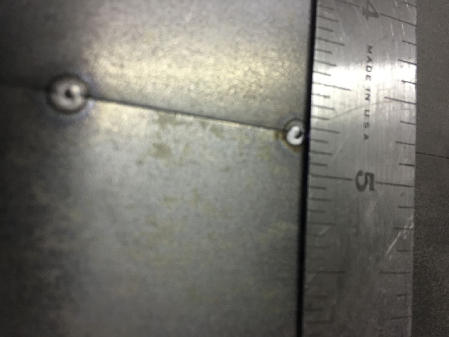 Patches started out flat and for the most part remained so.. 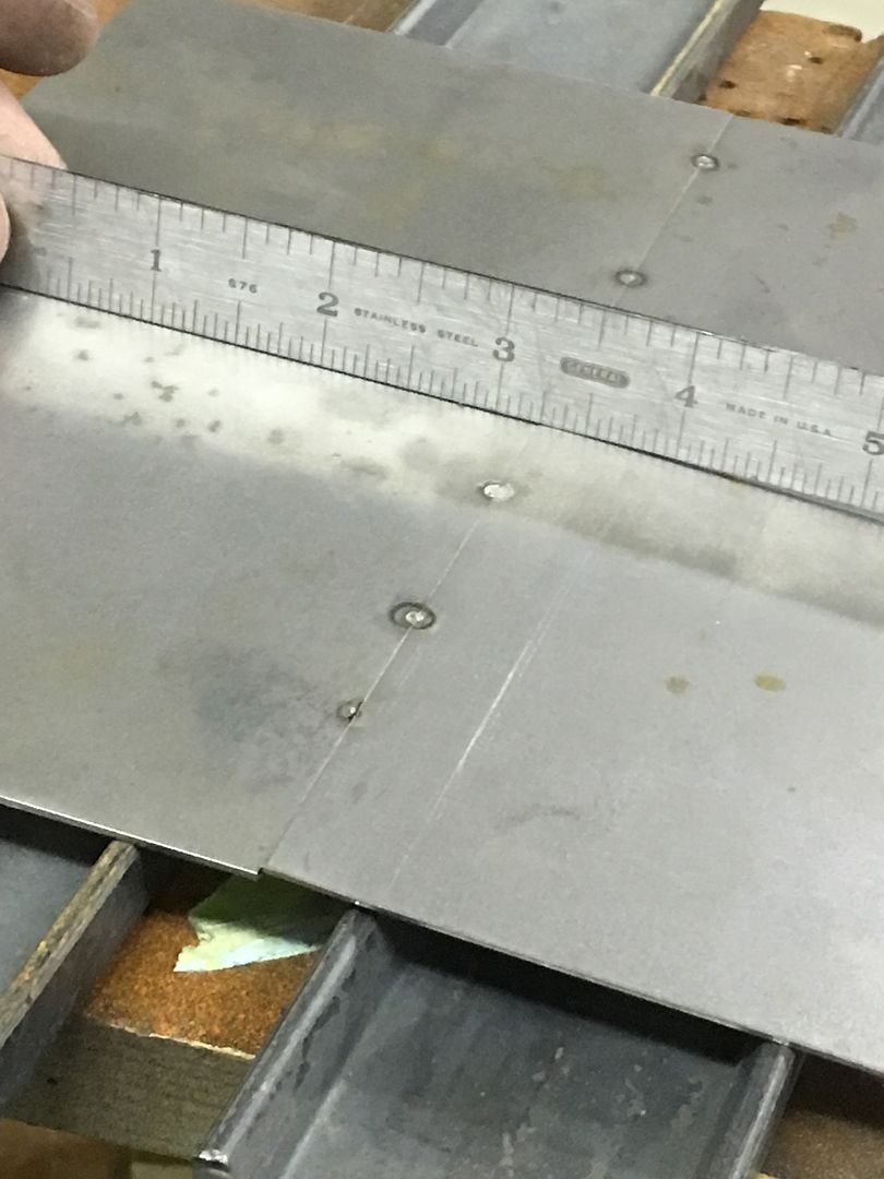 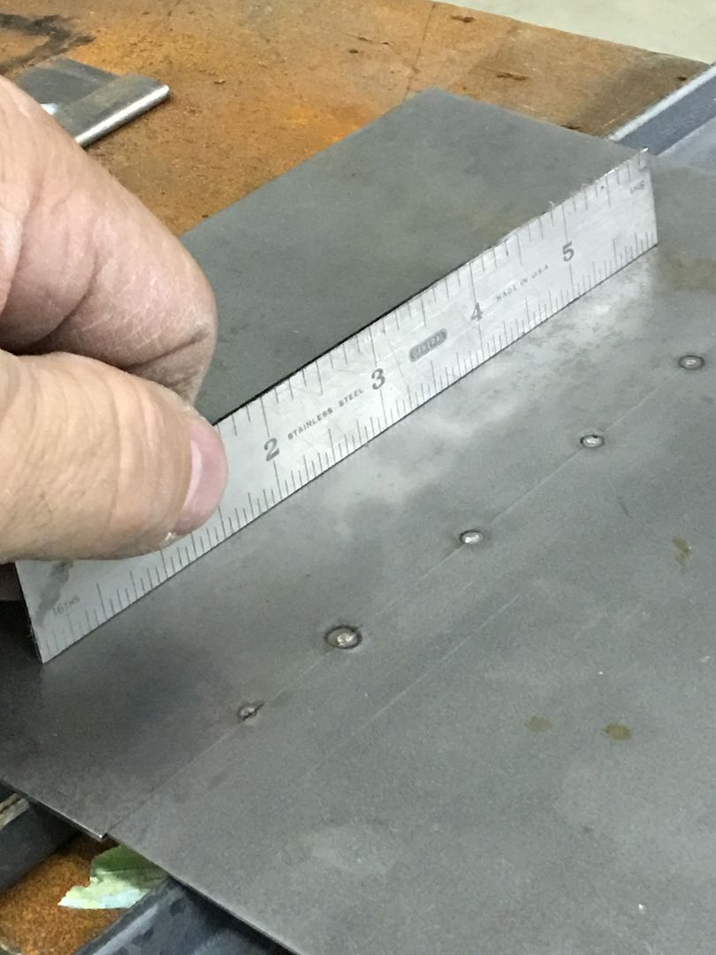 Adding a weld pass we are quick to see some distortion... 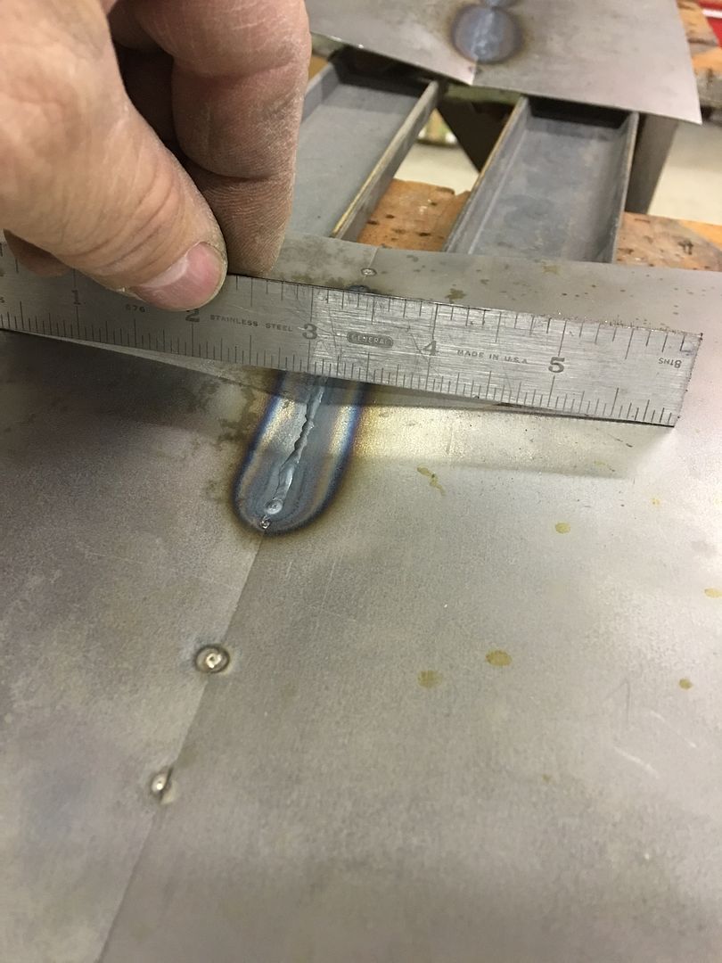 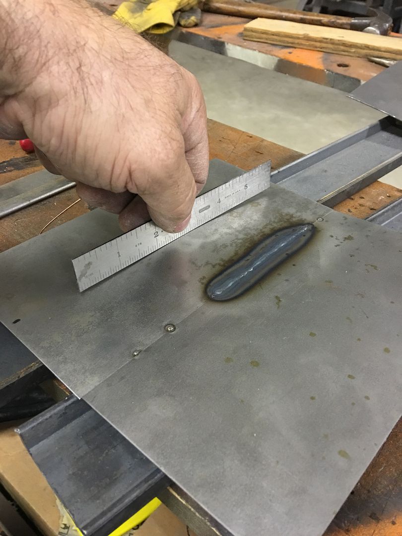 Examining this further, even though we have absolutely tight gaps for less instance of the panels pulling together, we still see distortion.. This is your typical weld shrinkage as the weld cools. Note in the next picture the panel is still fairly flat along the edges (red line), some shrinking at the weld (yellow arrows) and show a dramatic pucker between the two. Note that the weld has yet to be planished, so the weld shrinkage is pulling the metal alongside it together, the areas unaffected by heat remain largely unchanged (red line) and the area between the two are forming a bulge due to these differing forces. Here we address the problem, not the result. Planish out the weld to stretch it in length and the bulge will disappear. Don't make a habit of chasing the result, a shrinking disc on the bulge is not the correct resolution; if this were a crowned panel that action would be causing a severe low area. 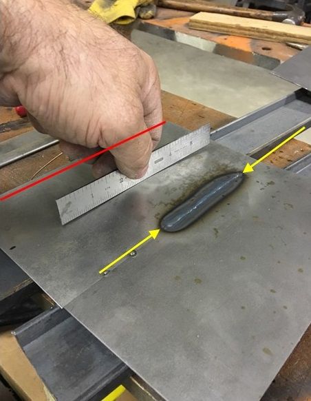 Referring back to an earlier statement I made on weld location: ......let's try this same scenario using a crowned sample near a body crease so we can take advantage of all 3 choices... 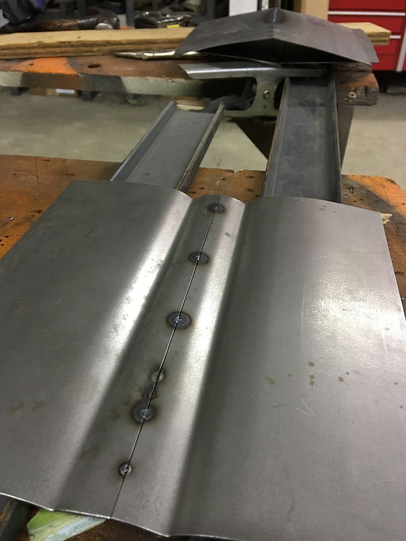 Weld pass.... 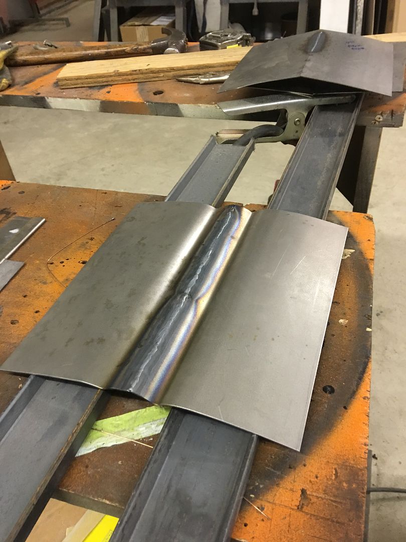 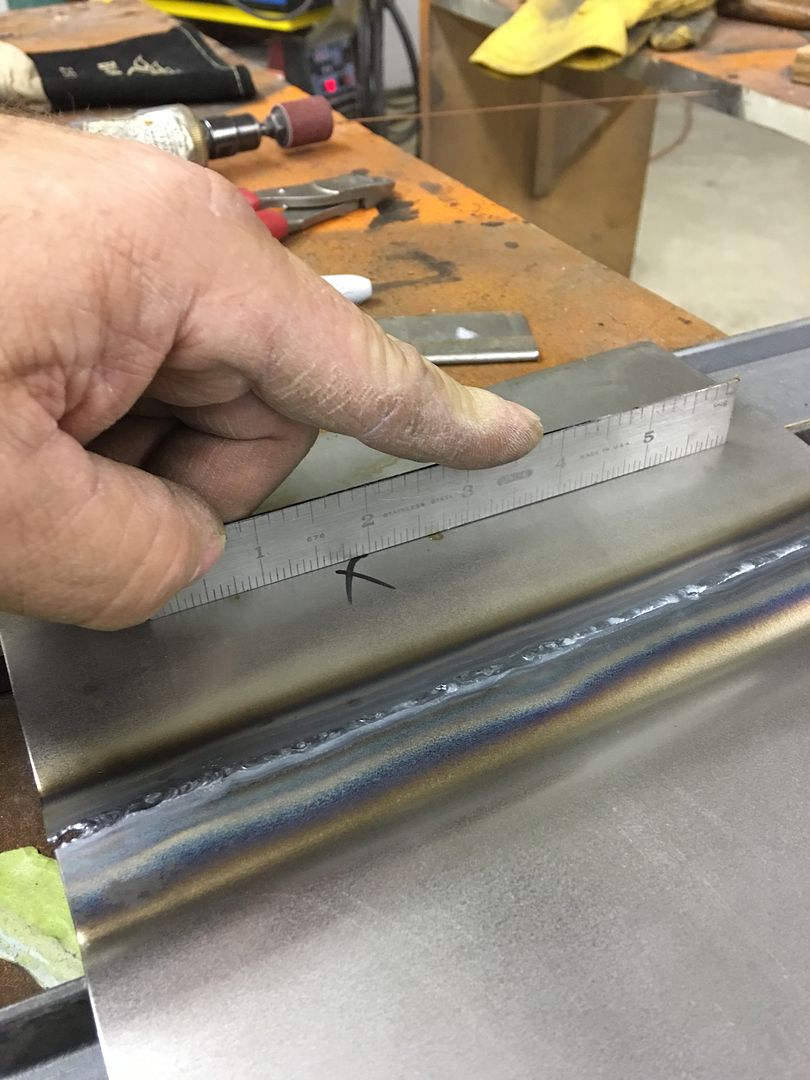 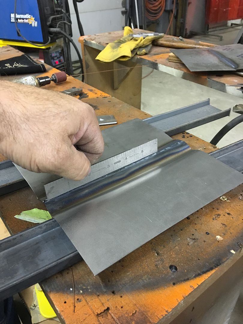 Here we can see how the weld location and panel features (crown, body crease) helped to control and limit any warping effects. The weld will still need planishing to restore the crown of the center bead, as no doubt it has pulled in slightly, but this is hands down a dramatic improvement over the flat "patches" we did the first time. This shows how these features in your body panels can help out in controlling weld distortion, so take advantage of these in weld location and leave the limiting of panel size as your absolute last consideration.
__________________
Robert Last edited by MP&C; 04-01-2021 at 06:23 AM. |
|
|
|
|
04-01-2021, 06:36 AM
|
#5 |
|
Registered User
Join Date: May 2013
Location: You're the only 10 I see
Posts: 367
|
Re: Roof patch causing warp / oil canning
Thanks for the detailed response and the additional info Robert.
The antenna cable was fished through to drivers pillar and the hole did not go through the inner panel. My truck does not have a cargo light or any other way to get behind this patch. In my first attempt, I definitely had some gaps in my patch, and was blowing holes and turned my welder heat and wire speed down low, so it seems I had a major offense in at least two categories. I am not familiar with planishing techniques, is this something I will need to do if I cant get behind the patch? Once I get my circle patch cut, is there a recommendation for what order to tack in?
__________________
1972 C20 |
|
|
|
|
| Bookmarks |
|
|


 Hybrid Mode
