
|
Register or Log In To remove these advertisements. |
|
|
|
|||||||
 |
|
|
Thread Tools | Display Modes |
|
|
 01-28-2020, 04:32 PM
|
#1 |
|
Registered User
Join Date: May 2015
Location: Tukwila Washington
Posts: 373
|
Mechanical speedometer drive solution
How do I keep the mechanical speedometer if I replace the old transmission with a modern unit with reluctor ring?
Use an electric motor to drive the speedometer. I have been working on this for a couple months now. I found a 17 page discussion that spanned several years. Someone had a working prototype, but failed to share any relevent information, and then vanished. Break down what needs to be done: 1. Identify a motor that will function at a slow speed and have a range of speed wide enough. 2. Analyze the signals in a vehicle. 3. Build a motor controller to drive the motor from the vehicle signal. 4. Assemble the parts including speedometer cable. Im using an 88 GMC K2500 for a frame swap for a 47 panel truck. I needed a truck for work around my house, so I got a 90 K1500 basically the same setup as the GMC. Im using the K1500 to look at signals, and eventually to test the 47 speedometer. A fair amount of math is involved, and I try to double check the convoluted equations. Please let me know if something is off! The reluctor ring creates 40 pulses per driveshaft revolution. The DRAC converts the 40 pulses to 128,000 pulses per mile for the RWAL Brakes, 4,000 pulses per mile for cruise control, and 2,000 pulses per mile for the ECM. Use the 2,000 ppm for the speedometer motor control. Look at the signal on that wire:
__________________
'47 Panel to '88 K2500 Frame Swap Mechanical Speedometer Drive Solution 1947.2 1 ton Chevy Panel 1955.2 Chevy 6700 Bus/RV 1990 Chevy K1500 |

|

|
|
01-28-2020, 04:33 PM
|
#2 |
|
Registered User
Join Date: May 2015
Location: Tukwila Washington
Posts: 373
|
Re: Mechanical speedometer drive solution
This is a screen shot of the oscilloscope, the truck is idling in 2nd gear at 10mph(on jackstands).
Channel 1 is the 2000ppm Channel 3 is the 40 tooth Reluctor Ring that produces 40 pulses per driveshaft revolution. Looking at the ch.1 2000ppm signal, one cycle is about 7 horizontal divisions. The time is set at 25ms. The period of one cycle is 7 x 25ms= 175ms, Frequency = 1/period, so 1/175ms, or 1/.175 = 5.71Hz This is close to the reading on another screenshot of 5.1Hz, so the math is correct. 60mph = 1 mile per minute, 10mph = 0.1666 miles per minute (10mph/60minutes = 0.1666) so 0.1666 x 60 = 10. And 1 mile in 6 minutes 2000ppm at 5.71Hz, or 5.71 cycles per second x 60 = 342.6 cycles per minute, or 342.6 pulses per minute 342.6 x 60 = 20,556 pulses per hour. At 10mph, 20,556/10= 2,055.6ppm. With some margin of error, close to 2000ppm. So for 10mph, the vehicle travels 1 mile in 6 minutes, and at (2000ppmile/6minutes) = 333.333ppminute. Thus at 10mph the vehicle travels for 1 minute a distance of 0.1666 miles with 333.333pulses. Lets check this: 333.333ppminute/60seconds = 5.555cps, or 5.555Hz, thats close to the measured 5.71Hz. At 60mph the vehicle travels 1 mile in 1 minute and 2000ppmile. 2000ppm/60seconds = 33.333Hz At 20mph take 60minutes/20mph = 3, the vehicle travels 1 mile in 3 minutes. At 2000ppm/3minutes = 666.666ppminute. 666.666ppminute/60seconds=11.111Hz So at 20mph, the vehicle travels .333 miles in 1 minute with a fequency of 11.11Hz on the 2000ppm signal. With this math, a chart can be produced for the 2000ppm signal:
__________________
'47 Panel to '88 K2500 Frame Swap Mechanical Speedometer Drive Solution 1947.2 1 ton Chevy Panel 1955.2 Chevy 6700 Bus/RV 1990 Chevy K1500 |
|
|
|
|
01-28-2020, 04:34 PM
|
#3 |
|
Registered User
Join Date: May 2015
Location: Tukwila Washington
Posts: 373
|
Re: Mechanical speedometer drive solution
GM old standard was always 1000cableRPM = 60MPH. Start dividing by 2 and get down to 2MPH needs about 33RPM.
(1000RPM=60MPH)/30= (33.3RPM=2MPH) 1000 Revolutions per minute = 60MPH, and 60MPH = 1 Mile per Minute so 1000 Revolutions per minute = 1000 Revolutions per mile How to get 2000 pulses per mile 12 volt square wave to drive the motor 1000RPM? At 60MPH, 2000 ppmile = 2000 ppminute. So (60MPH=2000ppMin)/30 = (2MPH=66.6ppMin), and 66.6ppMin/60seconds = 1.11ppSecond, or 1.11Hz 1000cable revolutions per minute = 2000 pulses per mile at 60 miles per hour, so 1.11Hz = 33.3RPM at 2MPH. Ill need to take the 1.11Hz signal from the DRAC and convert that to drive my motor 33.3RPM at 2MPH. We need an electric motor capable of starting around 15RPM that can increase to something above 1000RPM. I set up a test jig and tried several motors:
__________________
'47 Panel to '88 K2500 Frame Swap Mechanical Speedometer Drive Solution 1947.2 1 ton Chevy Panel 1955.2 Chevy 6700 Bus/RV 1990 Chevy K1500 |
|
|
|
|
01-28-2020, 04:35 PM
|
#4 |
|
Registered User
Join Date: May 2015
Location: Tukwila Washington
Posts: 373
|
Re: Mechanical speedometer drive solution
The arduino supplies a variable drive signal that controls a darlington pair, the motor is connected to 12v and the darlington pair. The RPM sensor reads the reflective flag on the motor and sends a signal to the oscilloscope.
Makita Driver: The driver can start and run slow:
__________________
'47 Panel to '88 K2500 Frame Swap Mechanical Speedometer Drive Solution 1947.2 1 ton Chevy Panel 1955.2 Chevy 6700 Bus/RV 1990 Chevy K1500 |
|
|
|
|
01-28-2020, 04:35 PM
|
#5 |
|
Registered User
Join Date: May 2015
Location: Tukwila Washington
Posts: 373
|
Re: Mechanical speedometer drive solution
.5145*60= 30.87rpm
Makita fast:
__________________
'47 Panel to '88 K2500 Frame Swap Mechanical Speedometer Drive Solution 1947.2 1 ton Chevy Panel 1955.2 Chevy 6700 Bus/RV 1990 Chevy K1500 |
|
|
|
|
01-28-2020, 04:36 PM
|
#6 |
|
Registered User
Join Date: May 2015
Location: Tukwila Washington
Posts: 373
|
Re: Mechanical speedometer drive solution
20.76*60= 1,245.6rpm
The Makita driver is the correct range for the speedometer driver. How to derive vehicle speed from motor speed: (1000rpm/30)=33.3rpm, so (1000rpm/33.3rpm)=30 take this result and divide into 60mph: (60mph/30)=2mph Lets look at our test results: The Makita Slow: (1000rpm/30.87rpm)=32.39 and (60mph/32.39)=1.85mph The Makita Fast: (1000rpm/1,245.6rpm)=0.80 and (60mph/0.80)=75mph The Makita driver is a work tool, so I went to the second hand store to find a good deal on a cordless driver. I found a Chicago Electric driver. I extracted the motor, but it was too fast. I put the planetary gear back on and that got it in the ball park. Chicago Electric w/Planetary Gear:
__________________
'47 Panel to '88 K2500 Frame Swap Mechanical Speedometer Drive Solution 1947.2 1 ton Chevy Panel 1955.2 Chevy 6700 Bus/RV 1990 Chevy K1500 |
|
|
|
|
01-28-2020, 05:42 PM
|
#7 |
|
Post Whore
  Join Date: May 2015
Location: Alabama
Posts: 14,585
|
Re: Mechanical speedometer drive solution
looks like you know your stuff......waaaayyyy over my head...
me..i just get a Dakota digital convertor box and move on...
__________________
Mongo...aka Greg RIP Dad RIP Jesse 1981 C30 LQ9 NV4500..http://67-72chevytrucks.com/vboard/s...d.php?t=753598 Mongos AD- LS3 TR6060...http://67-72chevytrucks.com/vboard/s...34#post8522334 Columbus..the 1957 IH 4x4...http://67-72chevytrucks.com/vboard/s...63#post8082563 2023 Chevy Z71..daily driver |
|
|
|
|
01-28-2020, 07:02 PM
|
#8 | |
|
Senior Member
 Join Date: Feb 2014
Location: new smyrna beach fl / 29 palms cal
Posts: 1,727
|
Re: Mechanical speedometer drive solution
Quote:
__________________
Hand made A/C vent manifolds for 64-66 trucks adapts any aftermarket A/C to OEM vent |
|
|
|
|
|
01-28-2020, 07:25 PM
|
#9 |
|
Registered User
Join Date: Jun 2016
Location: Phoenix AZ
Posts: 429
|
Re: Mechanical speedometer drive solution
I’ve been wanting to do something like this with a stepper motor. That’s is supposed to be used in the speedos anyway. I just lost interest.
You can get arduino clones for cheap. |
|
|
|
|
01-28-2020, 10:42 PM
|
#10 | ||
|
Senior Member
 Join Date: Jul 2009
Location: Athens, AL
Posts: 499
|
Re: Mechanical speedometer drive solution
Quote:
Quote:
|
||
|
|
|
|
01-29-2020, 12:37 PM
|
#11 | |
|
Registered User
Join Date: May 2015
Location: Tukwila Washington
Posts: 373
|
Re: Mechanical speedometer drive solution
Quote:
Very generous offer, Thanks! PM sent. I'm interested in comparing the different motors and how the speedo reacts. Once I get the circuit down, I can take the IC off the arduino, and mount it to a new pcb.
__________________
'47 Panel to '88 K2500 Frame Swap Mechanical Speedometer Drive Solution 1947.2 1 ton Chevy Panel 1955.2 Chevy 6700 Bus/RV 1990 Chevy K1500 |
|
|
|
|
|
01-28-2020, 05:58 PM
|
#12 |
|
Registered User
Join Date: Sep 2018
Location: Hampden, ME
Posts: 406
|
Re: Mechanical speedometer drive solution
I love this at home hacking stuff. I haven't messed a bunch with the arduino's yet but keep wanting to pick up a basic kit and try it out.
I just ended up using the OBDII port, a bluetooth sender, and will be using a tablet for my gauges. |
|
|
|
|
02-05-2020, 10:22 PM
|
#13 |
|
Registered User
Join Date: Feb 2016
Location: Portland OR
Posts: 154
|
Re: Mechanical speedometer drive solution
Dakota Digital pulse sensor works just fine in mine as Mongo stated.
|
|
|
|
|
02-06-2020, 10:53 AM
|
#14 |
|
Registered User
Join Date: Dec 2002
Location: Cactus Patch So. Az
Posts: 4,749
|
Re: Mechanical speedometer drive solution
D D after you get past the price it works great and easy to install!
__________________
53 TuTone Extended Cab 350 4-Spd 3:08 (SOLD) 53 Chevy Moldy pearl green ZZ-4 4L60E 9" 3:25 55 GMC 1st Black Mll (ZZ4) ZZ6 TKO 600 5 sp 3:73 62 Solidaxle Corvette Roman Red (327 340hp 4spd 3:36) C4 & C5 suspension tube chassis LS 3 4L70E 65 Corvette Coupe 327 350hp 4spd 4:11 78 Black Silverado SWB (350/350) 5.3 & 4L60E 3:42 2000 S-Type 3.0 (wife cruiser) 2003 GMC SCSB 5.3 4L60E 3:42 |
|
|
|
|
02-06-2020, 12:20 PM
|
#15 |
|
Registered User
Join Date: Feb 2016
Location: Portland OR
Posts: 154
|
Re: Mechanical speedometer drive solution
The pulse sensor is $40-$50, I didn't do the digital gauges that are $1000.
|
|
|
|
|
02-06-2020, 03:27 PM
|
#16 |
|
Registered User
Join Date: May 2015
Location: Tukwila Washington
Posts: 373
|
Re: Mechanical speedometer drive solution
My initial plan was to use an off the shelf solution, I found a couple available. In my search I also found discussions of building your own. I also discovered that I can replace the tail housing and use a mechanical speedometer cable, there are several signal sensors with pass through for mechanical cable available. Its good to have options. Im having fun playing with electronics.
I received the motor from Dayj1, Thanks again! It is a DC motor with optical disk, not a stepper. I found it is used in a Lexmark printer for paper feed. It does run at 2,136rpm for 128mph, but I couldnt get it to run slower than 160rpm that works out to 9.6mph. I could gear it down, but 1.5:1 would get 6.4mph to 85mph. I like that it has the optical disk, Ill play with that. Part of the issue could be my test setup, Im using a BJT transistor for the motor supply, a FET might be better. The PWM is 12v, I could try different frequencies, or voltages. I may fine tune it at some point, but it works for now. Someone tore apart a broken vacuum at my work, I found the motor in the scrap bin. Its from a Dyson cordless, unfortunately the shaft was bent. It kind of worked, I tried to unbend the shaft, and it has a good range, but too fast at 100rpm to 8,000rpm . The shaft is 2.3mm and I have some gears from the hobby shop for 2mm. I set it up with 5.5:1 gears and its good for 3mph to 100mph. It is a Johnson motor, but I was unable to cross reference the numbers on their website. I did locate a similar motor by looking at size and supply voltage. There is also the spec. of Stall Torque, that may be related to how slow it will run. Ill order a few different motors to test. Im still curious about using a stepper motor, so Ill keep searching. The code has some bugs and needs to be cleaned up, but it works for 2Hz and up. Im ready to connect my speedometer to these motors to see how it effects the motors. It looks simple enough to build a DRAC. I can use an op-amp as a Schmitt trigger to clean up the VSS signal and produce a nice square wave.
__________________
'47 Panel to '88 K2500 Frame Swap Mechanical Speedometer Drive Solution 1947.2 1 ton Chevy Panel 1955.2 Chevy 6700 Bus/RV 1990 Chevy K1500 |
|
|
|
|
02-06-2020, 03:29 PM
|
#17 |
|
Registered User
Join Date: May 2015
Location: Tukwila Washington
Posts: 373
|
Re: Mechanical speedometer drive solution
A 5volt regulator to feed the square wave into the Arduino. The signal can be converted from 40 pulse per driveshaft rev to 128,000ppm, 4,000ppm and 2,000ppm in the software. A potentiometer can be used to adjust for tire size and gear ratio. The 128,000ppm looks like a modified square wave on my truck, A differentiator will produce that signal. It looks like the 4,000ppm is 5v, and the 2,000ppm is 12v. The Arduino operates at 5v so a transistor switch can bump the signal up to 12v.
Ill need to order some components and breadboard this. Id like to set up a reluctor ring and sensor on my bench so I dont need to jack up the truck when Im trying to figure this out.
__________________
'47 Panel to '88 K2500 Frame Swap Mechanical Speedometer Drive Solution 1947.2 1 ton Chevy Panel 1955.2 Chevy 6700 Bus/RV 1990 Chevy K1500 |
|
|
|
|
02-08-2020, 12:28 PM
|
#18 |
|
Senior Member
Join Date: Dec 1999
Location: TX
Posts: 1,519
|
Re: Mechanical speedometer drive solution
Just found this thread, I actually started working on this also. I got sidetracked and haven't come back to it yet, but I'll post some pictures of my setup. DC Motor with Timing belt and gears that drive another shaft that has a rotary encoder. I used a Teensy development board instead of a real arduino. The rotatry encoded which Is not installed in my pictures and I can't seem to find right now is a CUI AMT103-V. The whole thing is designed to thread right on to the back of the speedometer head.
I kept smoking regular transistors, or they were not working right(can't remember) so that other little thing plugged into the board is a better surface mount transistor or mosfet. 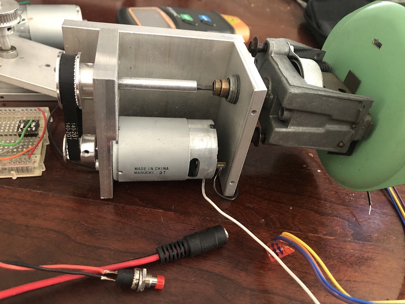 
|
|
|
|
|
06-14-2020, 11:05 PM
|
#19 |
|
Senior Member
Join Date: Jun 2019
Location: Midway USA Kentucky
Posts: 540
|
Re: Mechanical speedometer drive solution
Just stumbled across this thread you might want to go get a 95-97 S10 Speedo and convert it like LS1nova did.
http://67-72chevytrucks.com/vboard/s...d.php?t=512751 |
|
|
|
|
02-08-2020, 12:34 PM
|
#20 |
|
Senior Member
Join Date: Dec 1999
Location: TX
Posts: 1,519
|
Re: Mechanical speedometer drive solution
I don't have them here right now, but I bought that 40tooth reluctor wheel and VSS from a 4L60 to make a test setup so I could see what the actual signal looked like and to use for testing. I don't have an operational vehicle with the right output right now.
|
|
|
|
|
02-10-2020, 09:24 PM
|
#21 |
|
Registered User
Join Date: May 2015
Location: Tukwila Washington
Posts: 373
|
Re: Mechanical speedometer drive solution
Jason, Thanks for sharing! It looks like you have a solid mechanical setup. I like the drive belt youre using. I looked up the part number for the encoder you referenced, there were some documents about encoders, so I downloaded them. Ive got some reading to do!
Im using a bench power supply for the 12 volts. I had to set the current limit to 10 Amps to keep the 12v from dropping. The motor from the cordless driver is similar to the Mabuchi motor, they draw some current and have plenty of torque, more than enough. It may be better to under utilize a bigger motor(may run cooler, run more stable) than a smaller, but Ill test the smaller ones that I have also. My first attempt to run the motor fried a 6144 transistor with a TO-220 case, rated 10A, so I used another 6144 to drive a 7926 in a TO-3(metal can) case, rated 15A. These were just random components that I had on hand. I may choose an off the shelf alternative for a final build. Today I spent some time modifying my code to use a switch case format. I added flags for reverse and stationary. Now the PWM for the motor is off until the 0 to 60Hz signal (from the 2000ppm) goes above 1Hz. and the PWM turns off when that signal goes below 1Hz. Speedometer wont run when driving in Reverse. Some bugs at the upper end need to be worked out, the code for maximum speed is broken now. I dont have much experience with Floating-Point variables, but thats what Im using since the math to convert frequency to drive signal uses decimal places. I may be able to get away with less resolution if its too much trouble. After I fix the max speed issue, Ill look at the optical disk motor that Dayj1 sent. The signal from the optical disk may be able to be used to throttle the motor supply, allowing control over the slow speed, and get it to run slower. I dont have any experience with that, but after all that is what the optical disc is for.
__________________
'47 Panel to '88 K2500 Frame Swap Mechanical Speedometer Drive Solution 1947.2 1 ton Chevy Panel 1955.2 Chevy 6700 Bus/RV 1990 Chevy K1500 |
|
|
|
|
03-13-2020, 04:31 PM
|
#22 |
|
Registered User
Join Date: May 2015
Location: Tukwila Washington
Posts: 373
|
Re: Mechanical speedometer drive solution
I keep meaning to post an update and have put it off three times now, so here is the progress:
I was able to get a consistent speed with the simple code for frequency input. The code for reading the optical disk is the same as the code for detecting input frequency, but I was having delay issues. I couldnt find any examples of code with both frequency input and an optical disk. I read that using Interrupts is the way to go for reading an encoder, so I implemented the code, sharing timer resources. The results were way off, then I remembered reading something about Floating-point variables taking too much time. I set the variables as Integers, and now the motor speed is controlled by the input frequency, and the optical disk produces a clean output frequency. The next step is to scale the output frequency from the optical disk to the input drive frequency. This action will turn the dc motor into a Servo motor. The input frequency will determine the speed of the motor, the encoder frequency will be used to keep the speed consistent. This should translate to meaning the speedometer needle will not flutter or bounce. I have yet to connect the speedometer to any motor as this programming is getting deep. The speedometer will be a light load that will not change, so the motor speed shouldnt be affected by the load. The motor speed might change after the motor gets hot, that is yet to be determined. The optical disk will help maintain a steady speed. Im interested in using it to control the low end speed. I have read that speeds below 10mph can be problematic with the off-the-shelf products available. The motor needs to have a wide enough range for 0 to 90mph or higher, and be able to run slow. Using gears reduces the slow speed, but it also lowers the top speed. The Arduino PWM is at a set frequency. The motor needs a minimum supply to start turning, that works out to be around 5mph. Ill try to write some code that gets the motor spinning, but keeps it moving at a slower rpm. Basically, Ill use the minimum PWM signal to get the motor spinning, and toggle the PWM off and on. If that doesnt work, Ill get into PFM(Pulse Frequency Modulation). That will require manipulating the registers of the microproccessor on the Arduino to change the clock speed. Reclocking through machine language. This will also alter the clock signal that is used to read the input frequency, and optical disk, so that will have to be compensated. Murky territory that I would prefer to avoid. I have been struggling with the code, but making some progress. The timing for the Optical read <+.3%error with using Interrupts. The timing for the input frequency was greater than up to 20% with using interrupts, may be due to to frequency range of 1Hz to 60Hz. Polling the pin state yields <+.1%error for the timing of the input frequency, so I wont use interrupts to read the input frequency. The Optical disk has 64 holes, so the ratio between optical disk frequency and the input frequency works out to something like 50:1. I wasnt seeing much servo action, the motor drive frequency is updated every second with the code, and the optical disk frequency is also updated every second. Im using the arduino Serial Monitor on my pc to troubleshoot the code. The input frequency matches what the fuction generator is set at, 10Hz. The optical disk is fluctuating 414Hz. to 440Hz. That indicates the motor speed is fluctuating. I took about 10 samples at each input setting from 7Hz to 63Hz. I put all the data into a spreadsheet. Divide the optical disk frequency by 64 and get RPM of the motor. Then divide the input frequency by RPM to get the multiplier. There are 315 samples with a multiplier from 1.09 to 2.94, so Add all the multipliers and divide by 315 to get 1.39. Now I start the motor, and then divide the input frequency by 1.39 and multiply that by 64. This gives me the target frequency. Compare this target frequency to the optical disk frequency, and the drive signal adjusts up or down. I take more samples at each frequency, but the optical disk frequency is still fluctuating, maybe less than before, and the motor can start at a slightly slower speed. So some progress. I thought a hydraulic motor might be a better solution. Run a couple lines from the power steering up under the dash, control the amount of pressure spinning the drive. The slow speeds wouldnt be a problem. Not finding any small hydraulic motors available, or economical. I did find some miniature RC excavators, that looks like an expensive hobby. I also found mention of PID controllers(Proportional/Integral/Derivative). So it looks like I am already building a PID controller, just didnt know it. Ill keep hacking away on this. Today, I decided to work on the slow speed. I turned off the PID part of the code. Using the optical count, a delay can be introduced at regular intervals. I tried a bunch of different combinations. With a delay of 30 microseconds every hole, the motor rotates at .308Hz, or 1.1mph. In effect it is a stepper motor. Now Ill have to develop this slow speed code and incorporate it into the PID.
__________________
'47 Panel to '88 K2500 Frame Swap Mechanical Speedometer Drive Solution 1947.2 1 ton Chevy Panel 1955.2 Chevy 6700 Bus/RV 1990 Chevy K1500 |
|
|
|
|
03-14-2020, 09:12 PM
|
#23 |
|
Registered User
Join Date: Aug 2013
Location: Tecumseh
Posts: 355
|
Re: Mechanical speedometer drive solution
Its not really that hard to do.
https://retromini.weebly.com/blog/arduino-speedometer I am working on a prototype that uses a $4 gps module. Put the servo motor behind and dash speedo faceplate and stick your needle on it. Adjust the code for your gears and tire size
__________________
Current project 1959 Willys = GEZR TRUK Geezer is a Latin compound word made up of two roots. Gee meaning Urine Stain and Zer meaning your pants are open! FMCDH GBU and GBA http://www.youtube.com/user/aknovaman/videos |
|
|
|
|
03-19-2020, 04:05 PM
|
#24 |
|
Registered User
Join Date: May 2015
Location: Tukwila Washington
Posts: 373
|
Re: Mechanical speedometer drive solution
ANKNOVAMAN, Thanks for the link! Another link from that post: http://andydoz.blogspot.co.uk/2017/1...ronic-gps.html
Its nice to see a working example of some code, the similarities show me Im getting part of it right. I have considered going this route, but I wanted to retain the mechanical odometer. My 88 GMC does have a motor for the odometer, so it could be done. I read through this epic thread started by ls1nova71: http://67-72chevytrucks.com/vboard/s...d.php?t=512751 before I decided to start This thread. At first I thought about having a motor in a box connected to the speedometer cable. Thanks to Dayj1 for the motor, and Jason Banks for the mounting example now Im getting the idea that the motor can be attached directly to the speedometer without gear reduction, or a cable.
__________________
'47 Panel to '88 K2500 Frame Swap Mechanical Speedometer Drive Solution 1947.2 1 ton Chevy Panel 1955.2 Chevy 6700 Bus/RV 1990 Chevy K1500 |
|
|
|
|
03-19-2020, 04:12 PM
|
#25 |
|
Registered User
Join Date: Aug 2013
Location: Tecumseh
Posts: 355
|
Re: Mechanical speedometer drive solution
I have a functional stepper that responds to the analog input to the Arduino so I know my connections and code are good. Last night, I connected the stepper and GPS module, loaded the retro-mini code; looks good so far. I plan to test it outdoors this weekend.
__________________
Current project 1959 Willys = GEZR TRUK Geezer is a Latin compound word made up of two roots. Gee meaning Urine Stain and Zer meaning your pants are open! FMCDH GBU and GBA http://www.youtube.com/user/aknovaman/videos |
|
|
|
|
| Bookmarks |
|
|


 Hybrid Mode
