
|
Register or Log In To remove these advertisements. |
|
|
|
|||||||
 |
|
|
Thread Tools | Display Modes |
 09-26-2018, 12:44 PM
|
#1 |
|
Registered User
Join Date: Oct 2014
Location: Chattanooga TN
Posts: 75
|
More help with dash wiring 1970 C10
http://outintheshop.com/faq/wiring/wiring.htm
I'm having a hard time figuring out what the 12/20 gauge pink wires are for. Mine is wired like this, but the engine harness is missing on my truck and will have to be replaced. It's got a 12P coming from the bulkhead, splitting between the fuse panel and the ignition switch. From the fuse panel a 20P wire goes to the cluster connection. The diagram linked shows the 20P is the fuel gauge feed, but how? The wire coming from the fuel gauge is tan. And what is the 12P supposed to mate to on the engine harness? The diagram shows 20W /OR/ PPL that goes to the starter/coil. What is this for? 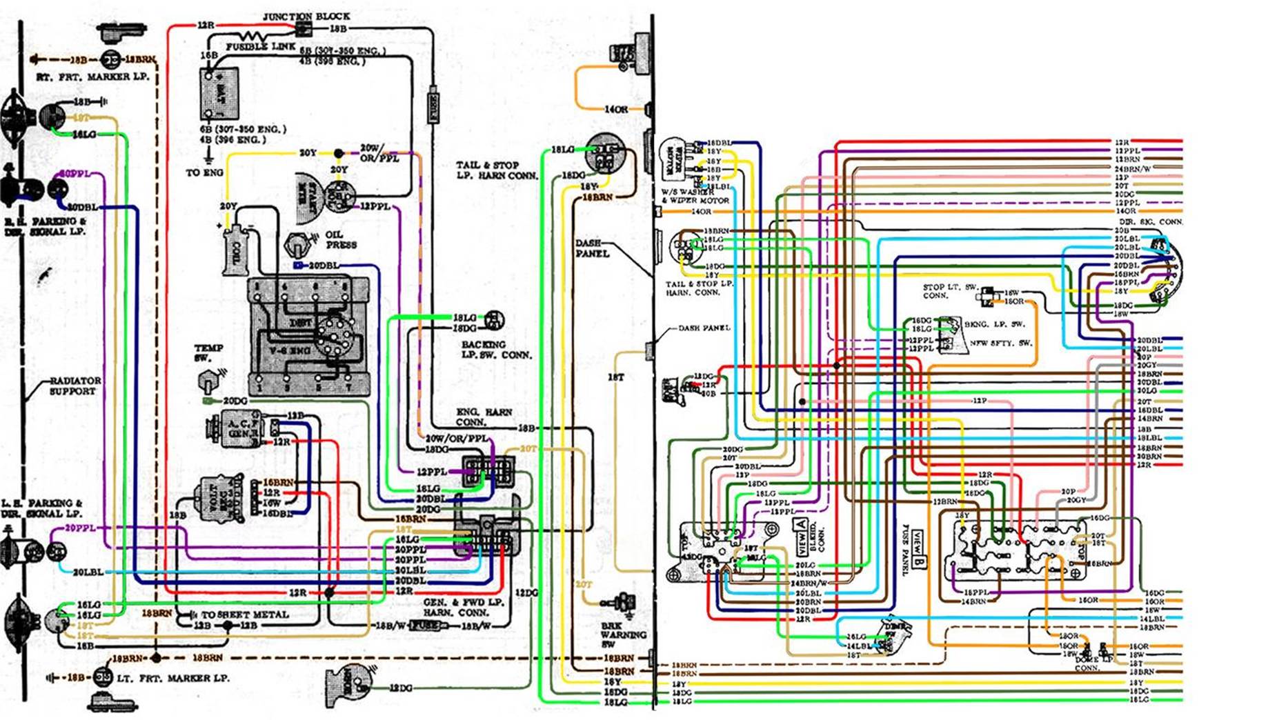
|

|

|
|
09-26-2018, 10:23 PM
|
#2 |
|
Msgt USAF Ret
  Join Date: Jan 2005
Location: Kalamazoo, Michigan
Posts: 8,703
|
Re: More help with dash wiring 1970 C10
.The 12 pink wire doesn't come from the firewall block. It originates at the key switch and is fed off the red wire from the battery, alternator junction in the engine harness, which you don't have.
The 12 gauge pink wire from the key splits and one wire goes to the firewall block and the other wire goes to the fuse panel to power all the fused accessories including the IgN Unfused terminals in the fuse block. The first wire to the firewall block is the ignition wire for the old stock coil and it carries a full 12 volts from the ignition switch. The coil isn't designed to run on 12 volts during normal engine operation so a resistance wire is incorporated to step down the voltage going to the coil. The other side of the pink wire in the firewall block is a resistance wire which is a 20 gauge white/orange/ purple wire shown in your diagram. As you can see in the diagram, one end of the whp wire goes to the coil and it is joined by a yellow wire at the starter which is connected to the starter solenoid on the R terminal. This wire feeds a full 12 volts to the coil for a hotter spark during starting and when the engine starts the w/o/p wire reverts back to the coil feed wire. It is a 1.8 ohm resistor and drops the coil voltage down to 8 to 9 volts. Looking at the fuse panel in the diagram you will notice the larger 12 gauge pink wire from the key switch and just to the right of it is a 20 gauge pink wire which is attached to the cluster feed fuse in the fuse panel. This is the pink wire that feeds power to the dash cluster and thence to the fuel gauge and also the temperature gauge, It is connected to the cluster plug wire in the no. 3 terminal on the plug for the Gauge clusters and to no. 7 in the idiot light panels. Here is a diagram for the light clusters that shows the pink feed wire. The wiring is different for the two clusters as shown by the gauge cluster at the very top and the light cluster in the middle of the diagram. Also notice the ignition switch just below the gauge cluster wiring in the top of the diagram and you can see the red 12 gauge wire coming in from the engine harness and the 12 gauge pink wire coming out of the key switch before it splits and goes to the inside of the firewall block and the fuse panel. BTW the red 12 gauge wire also splits after it comes through the firewall. It goes to the horn relay, the ignition switch the fuse panel and to the headlight switch.
__________________
VetteVet metallic green 67 stepside 74 corvette convertible 1965 Harley sportster 1995 Harley wide glide Growing old is hell, but it beats the alternative. |
|
|
|
|
09-27-2018, 09:01 AM
|
#3 |
|
Registered User
Join Date: Oct 2014
Location: Chattanooga TN
Posts: 75
|
Re: More help with dash wiring 1970 C10
Thank you!
Yes, I saw the 12R wire split between the horn relay, fuse panel, headlight switch and ignition switch. So with that said, I am converting my truck to gauges. I know from other threads the 20P wire moves on the cluster connection. Do I need to retain the 12P wire going to the firewall block? I am running an HEI distributor, if that makes a difference. |
|
|
|
|
09-27-2018, 12:30 PM
|
#4 |
|
Msgt USAF Ret
Join Date: Jan 2005
Location: Kalamazoo, Michigan
Posts: 8,703
|
Re: More help with dash wiring 1970 C10
On the stock trucks the 12 p wire is the main power feed wire from the battery and the alternator to the cab, so you will need to retain it, unless you plan to install a main junction in the engine bay or a more modern fuse panel. In either case a main power feed from the battery and alternator to the cab is imperative.
There are several electrical modifications that can be done to improve our trucks. HEI ignition. Internally regulated alternator. Headlight relay modification. Light panel to gauge panel. Electrical cooling fan. And some others. All of these modifications have been covered many times on the forum so there is more than enough information out there on the topics. Sadly the FAQ section on electrics could use some upgrading but I have saved many of the best threads for members who have not seen the ways to accomplish them. With that said, I would recommend that you decide how far you want to go so that you don't have to change the harness every time you want to add a modification. Most of these changes are relatively inexpensive and easy to do. The HEI distributor must be the easiest with headlight relay mods being the cheapest. We are all here to walk you through anything you wish to do and more than happy to do it. Here is a great example of how to convert to the dash gauge cluster. http://67-72chevytrucks.com/vboard/s...d.php?t=588853
__________________
VetteVet metallic green 67 stepside 74 corvette convertible 1965 Harley sportster 1995 Harley wide glide Growing old is hell, but it beats the alternative. |
|
|
|
|
09-27-2018, 01:43 PM
|
#5 |
|
Registered User
Join Date: Oct 2014
Location: Chattanooga TN
Posts: 75
|
Re: More help with dash wiring 1970 C10
Thanks again,
I thought the main power coming in was the 12 gauge red wire? I will be running an aftermarket electric fan, headlight relay harness, hei ignition and a 3 wire alternator. I'd planned on running a busbar under the hood next to the battery and a relay/fuse block next to that. I'm also planning on putting the horn relay under the hood. The interior harness should stay relatively the same, except for the modifications needed to use an OEM gauge cluster. So you are saying I need to retain the pink 12 gauge wire coming from the bulkhead and going to the fuse panel/gauge cluster, but on the engine side instead of having the resistance wire going to the coil I need to put a regular wire in there? What gauge would the hei require? |
|
|
|
|
09-27-2018, 03:13 PM
|
#6 |
|
Registered User
Join Date: Oct 2014
Location: Chattanooga TN
Posts: 75
|
Re: More help with dash wiring 1970 C10
Ok, I think I've found the part of the answer to my own question in another thread where you had previously posted
http://67-72chevytrucks.com/vboard/s...d.php?t=454737 So indeed I replace the resistance wire with a 12 gauge on the engine side of the harness that goes to the hei. So in that case the pink 12 gauge will remain on the inside, go from the ignition to the fuse box, and a 20 gauge pink wire will go from the fuse box to a relocated spot on the gauge cluster. |
|
|
|
|
09-27-2018, 09:06 PM
|
#7 | |
|
Msgt USAF Ret
Join Date: Jan 2005
Location: Kalamazoo, Michigan
Posts: 8,703
|
Re: More help with dash wiring 1970 C10
Quote:
 For all the members who would like to follow this most excellent thread by DMJ Lambert on the subject of the replacement of the resistor wire. Here you go. http://67-72chevytrucks.com/vboard/s...d.php?t=708975
__________________
VetteVet metallic green 67 stepside 74 corvette convertible 1965 Harley sportster 1995 Harley wide glide Growing old is hell, but it beats the alternative. |
|
|
|
|
|
| Bookmarks |
|
|


 Linear Mode

